1-3-2. Brushless DC Motor
The brushless DC motor has removed the brush and commutator, which used to be a shortcoming of the DC motor. The features of brushless DC motors are as follows:
<1> Permanent-magnet type: The permanent magnet for a field (on the stator side) and the armature winding (on the rotor side) of the permanent-magnet DC motor are exchanged with each other so that the permanent magnet is on the rotor side and the armature winding is on the stator side.
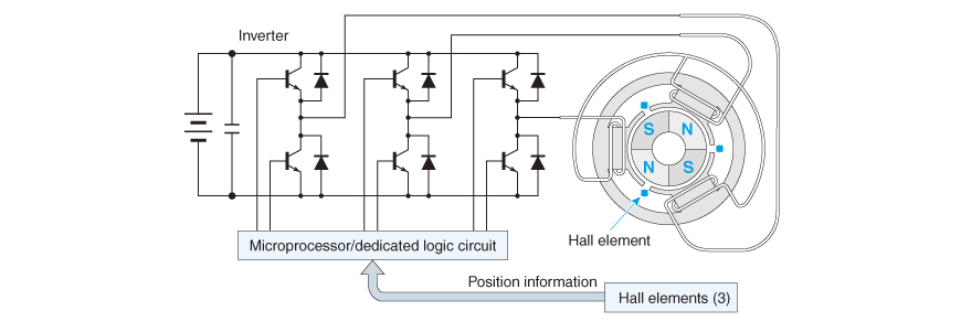
<2> Instead of power switching using the brush that works as the commutator position changes, Hall elements are used to detect the rotor position signal and feed the data back to the inverter in order to control energization.
This is a brushless DC motor. Fig. 1.7 shows the system configuration of a brushless DC motor.
Since drive voltage sent from the inverter is alternating current, there is a train of thought to classify this motor under AC motors as an AC-driven permanent-magnet synchronous motor. However, in this book, the brushless DC motor will be treated as a brushless DC motor of an independent field.
As the principle of rotation of this motor is similar to that of the DC motor, the relationship between the rotative force (torque) and speed is almost identical to that of the DC motor.
Inheriting the superb controllability of a DC motor as it is plus being brushless compared with the DC motor, this motor has a range of characteristics including its advantages in the areas of electromagnetic noise and product life cycle, high efficiency and energy-saving ability, high freedom of design and the ease of designing machine incorporation, etc. By fully exploiting these advantages, the DC brushless motor is widely applied to HDDs (Hard Disk Drives), CD-ROM drives and other information-processing equipment, refrigerators, washing machines, and other home appliances.
In the early stage of development of brushless DC motors, distributed winding was used for the stator winding. Today, concentrated winding is most commonly used. For the distributed and concentrated windings, please refer to the column titled "Distributed winding and concentrated winding".
This motor is also classified into the following according to the difference in the method used to install permanent magnets to the rotor:
- (1) SPM (Surface Permanent Magnet)
- (2) IPM (Interior Permanent Magnet)
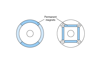
Surface permanent magnet: The SPM type has permanent magnets attached to the circumference of the rotor (see Fig. 1.8).
Interior permanent magnet: Fig. 1.8 (Right) shows a cross-sectional structure of an IPM type motor. For the IPM type, various methods of embedding permanent magnets are applicable. The purpose of the IPM structure is to reduce the risk of a magnet being peeled off by centrifugal force, and to take advantage of reluctance torque (read the later section on the switched reluctance motor).
Another classification method focuses on whether the motor uses a sensor such as a Hall element or rotary encoder to detect the SPM or IPM pole position, or whether it omits such detection (sensorless drive).
When the brushless DC motor is installed as an actuator, the main motor, drive inverter, and the control circuit, etc. are packaged in a very compact manner. An actual example is shown in Fig. 1.9.
The IPM type is adopted in order to prevent the magnet from being peeled off by the centrifugal force, and to take advantage of reluctance torque.
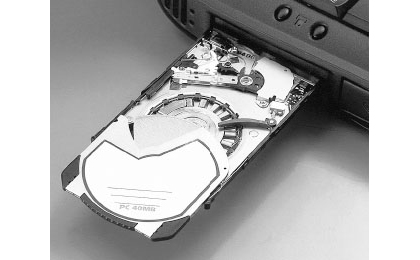
The thickness of the motor itself is 2 mm.
Distributed winding and concentrated winding
Fig. 1.10 shows a case where a 24-slot stator has (a) four poles and (b) eight poles. This method of changing the number of poles by switching the coil connection is not commonly used today due to low performance resulting from its complicated operation methods.
Meanwhile, as Fig. 1.11 shows, in the case of a six-coil concentrated winding stator, it can be converted to (a) two-pole, (b) four-pole, or (c) eight-pole motor by changing the wire connection despite the smaller number of slots.
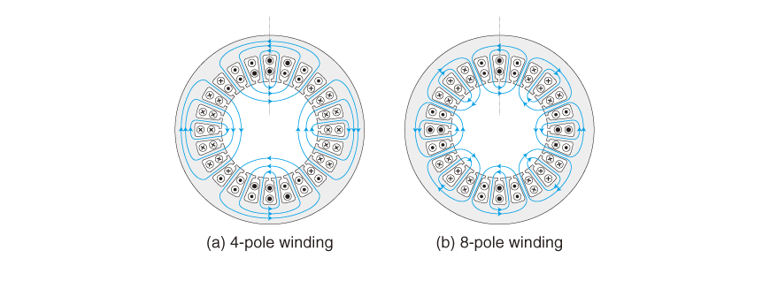
In the case of a 24-slot stator, various numbers of poles are possible. However, this book shows the cases of (a) four-pole winding and (b) eight-pole winding.
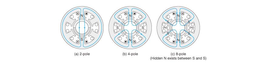
Despite the smaller number of slots, it can be converted into (a) two-pole, (b) four-pole, or (c) eight-pole motor by changing the wire connection.
The figure shows a case where the current is applied only to two coils in the U-phase. Although (b) and (c) are of the same wire connection, the figure shows that it can be a four- or an eight-pole motor according to the number of poles of the rotor. However, it is difficult to convert the stator into a six-pole motor.
Converter and inverter