2-1-2. Basics Rotation Principles
The ultimate goal of section 2-1 is to understand the principles of rotation for a DC motor with an iron core.
To do so, we need to have a basic knowledge about motors.
Therefore, we will consider a motor with no core rotor, similar to that described in natural science or physics textbooks.
At the same time, we will learn that a motor with no core is actually used in practice, not only in theory.
Nonetheless, the motto of this book is to teach "serious technology with ease." Instead of merely reviewing lessons, we will discuss topics that will help you carry out professional work.
BLI Law
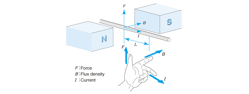
As demonstrated in Fig. 2.2, suppose there is magnetic field B in the air. When current I is applied to the wire placed across the field, force F is generated in the wire. The intensity of this force is given by the following equation, which is called the BLI law.
F = BLI ...... (2.1)
F: Force [N] B: Magnetic flux density [T]
L: Length of wire in the field [m] I: Current [A]
Moreover, the direction of force applied to the wire is in the direction shown in the figure according to Fleming's left-hand rule.
Regarding the corresponding relationship between your fingers and symbols, memorize it using "F, B, I" starting with the thumb, or going in reverse starting from the middle finger and moving toward the thumb using "Current, Field and Force".
Symbol B represents the intensity of magnetic field lines, and is called magnetic flux density. Magnetic field lines are not visible and therefore it is not possible to check directly. The International System of Unit (SI) of magnetic flux density is T (Tesla), which is equal to [Wb/m2] of MKS unit.
One tesla is the intensity of a magnetic field when magnetic flux of one weber [Wb] is present per square meter.
Another unit, gauss [G], is also used by physicists and magnet manufacturers. One T is equivalent to 10,000 G.
Principle of Rotation of Motors without Cores
When the wire is wound into a coil as shown in Fig. 2.3 and energized in the direction shown with current I, an upward force is generated to the left-hand side of the coil, and a downward force is generated to the right-hand side, which causes the coil to rotate. This is the principle of rotation of DC motors we learned in school.
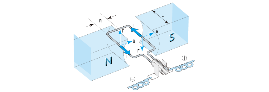
T = 2RF = 2RNBLI ...... (2.2)
T: Torque [Nm] R: Radius of rotation [m] N: Number of coil turns
L: Width of magnetic path [m]
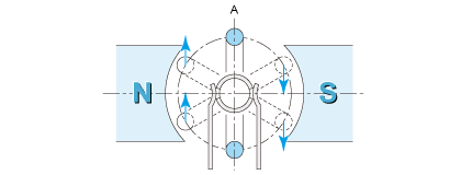
If only a set of coils is used, the rotation direction cannot be determined when the coil reaches position A in Fig. 2.4. So arrange for several coils and switch the current sequentially as the coils rotate, then the group of coils will rotate continuously.
First, consider a motor that has one single coil. When we consider the magnetic flux distribution, coil radius and length, and how current flows based on equation (2.2), torque T (rotative force) then can be expressed in proportion to current I according to the following equation. The coefficient of proportion KT is called a torque constant.
T = KTI ...... (2.3)
I: Coil current [A] KT: Torque constant [Nm/A]
This equation indicates that DC motor torque is proportional to the current. This is one of the very important characteristics of DC motors.
Torque constant will be expressed according to the following equation from equations (2.2) and (2.3):
KT = 2RNBL [Nm/A] ...... (2.4)
In the case of an actual motor, as seen in Fig. 2.16 (to be described later on), the motor has several coils connected like petals, and the current of the motor terminals flows inside the motor which is divided into two portions. At this time, let the number of turns of all coils be N, then the torque constant will be expressed by equation (2.4).
Assembling a clip motor
Let's assemble a simple motor, a clip motor that appears in school text books.
You can purchase materials from a stationery or hardware store.
For information on how to make it, see Fig. 2.5. Make a coil by winding enameled wire.
Enameled wire 0.4 to 0.6 mm in diameter should better be used, and the number of coil turns should be about 15 to 30. To wind neatly, use a PET bottle cap. After winding, keep in mind to adjust the coil so that it is as symmetrical to the rotation shaft as possible.
Care should be taken when removing enamel cladding at the ends of the coil. One side of the cladding should be completely removed, but only half of the cladding should be removed as the expanded view shows on the opposite side. This is the key point of clip motors.
Also be careful regarding the extent that enamel is removed as well as the angle toward the coil.
Insert the coil into a safety pin and lightly turn it in either direction. Then it will keep on turning.
If the coil is symmetrical, it will also turn in the reverse direction. If it is unbalanced, it will turn only in one direction.
Wind enameled wire 0.4 to 0.6 mm in diameter 15 to 30 times.
Remove enamel completely/Remove only half of the enamel cladding.
Insert the safety pin into rubber eraser.