2-1-6. Summary of Rotation Principle of DC Motor With a Core Slot
The following important conclusion is based on the analytical results described in reference material [1] with respect to DC motor torque.
In the torque calculation of a DC motor that has a slotted core, the BLI law seemingly holds.
In other words, supposing that the motor is an energy converter, some may think that the motor converts electrical energy directly into mechanical energy, while other may think that it converts electrical energy into electromagnetic energy, then to mechanical energy.
Whichever idea you may adopt, it is true that the amount of mechanical energy output from the motor while the rotor rotates once is the same. Consequently, we can conclude that the principle of torque generation of cored DC motors can also be explained by quoting the BLI law.
However, for more precise examination of factors such as torque non-uniformity due to the rotational position of the rotor, quoting the BLI law alone is insufficient, and analysis in consideration of magnetic flux concentration in the core would be required.
Summary of This Section
The following is a summary of the topics we have thus far examined with respect to DC motors:
- <1> Torque is proportional to current.
- <2> The rotating speed is determined by the balance between the motor terminal voltage and counter-electromotive force. If the load remains unchanged, higher the terminal voltage will be, faster the rotating speed will be.
- <3> If the terminal voltage remains unchanged, less the load will be, faster the rotating speed will be, and greater the load will be , slower the rotating speed will be.
- <4> If we explain the characteristics of a motor that has a slotted core by quoting a motor that does not have a core, the apparent characteristics of both motors will be the same.
Before closing this section, we will show, in Fig. 2.21, typical characteristics of DC motors observed when the terminal voltage is supposedly constant.
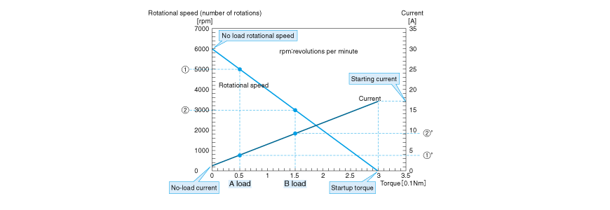
The figure shows two straight lines.
A straight line angled from top left to bottom right indicates the relationship between rotating speed and torque as explained in the section on speed.
With the straight line angled from top left to bottom right, the upper left-hand end represents the no-load rotating speed, and the lower right-hand end represents the startup torque.
The straight line angled from bottom left to the top right shows the relationship between torque and current. Motors cause friction loss due to the contact that occurs between the bearing and brushes even if they are making no-load rotations. If such loss is corrected, the torque and current are in a proportional relationship.
To give you an example, suppose a motor is running with load A. Numeral <1> is the rotating speed of the motor and <1'> is the current. Now, if the load condition changes to B, we understand that the rotating speed will be <2> and the current be <2'>.