2-2-3. Rotating a Brushless DC Motor
Using Semiconductor as Control Switch
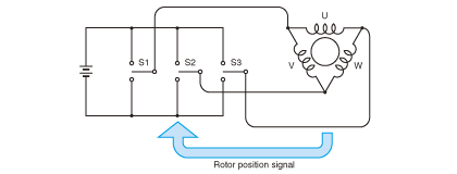
Switches S1 to S3 denote the rotor position signal
configured by transistors and/or MOSFETs.
A brushless DC motor that serves as a counterpart to a three-coil DC motor will be as shown in the preceding Fig. 2.23 (b).
If the principle of rotation of the brushless DC motor is identical to that of the DC motor, then the brushless DC motor should rotate as the DC motor does when energization is controlled.
Let us compare the situation by looking at Fig. 2.26 and Fig. 2.27.
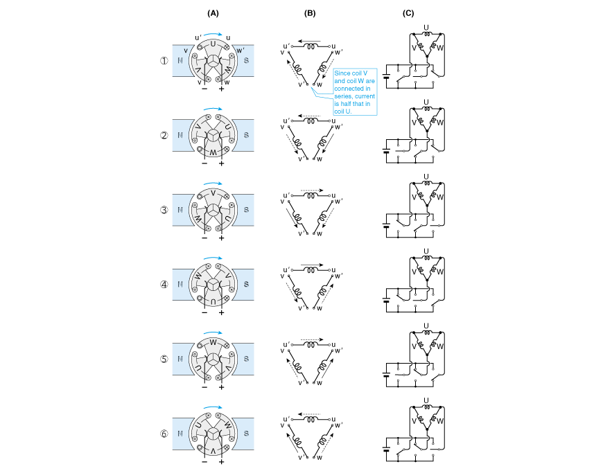
Here, let us name each coil in the three-coil DC motor U, V, and W, and the terminals of each coil u, u', v, v', w, and w' as the figure shows.
(A) shows the relationship among the coil, commutator, and brush at respective DC motor rotation angles.
The rotation of the rotor changes in a clockwise fashion from <1> to <6> as shown in the figure.
(B) shows the current flowing through the three coils at respective positions shown in (A). For example, in position <1>, coils V and W are in series. Therefore, the current that flows through coils V and W is half the current that flows through coil U. Broken lines indicate that the current is small.
(C) shows a method for changing over the coil current using a switch in the same way as illustrated in (B).
The brushless DC motor rotates based on the logic shown in (C) by using transistors and FETs as switches.