1-3-3. AC Motor
The term "alternating-current motor" is often described as "AC motor" in short. Therefore, we will follow this convention in this book.
AC motors are roughly classified into commutator motors, synchronous motors, and induction motors.
Synchronous and induction motors are both AC motors whose rotating speed is determined by the rotating magnetic field.
Here, the rotating magnetic field refers to a phenomenon where the magnetic field that is generated by applying three-phase, two-phase, or other multi-phase alternating current to the stator winding rotates at a speed determined by the frequency of the multiple-phase alternating current (= synchronous speed). The rotating magnetic field attracts the rotor, causing it to rotate. AC motors are classified according to the difference in rotation method.
Rotating magnetic field AC motors (generic term for synchronous and induction motors) are roughly classified into motors that run on the 100 VAC (the power supplied to households via two-wire service lines), and motors that use 200 VAC power (distributed to factories, etc. via three-wire lines).
The former is called a single-phase motor and the latter a three-phase motor.
Of late, three-phase motors are more frequently driven by the power inverter circuit using a semiconductor device called an inverter. The objective of this driver configuration is to operate the motor at a rotating speed and torque intended for the application by controlling the voltage and frequency through use of the inverter.
[3]-(1) Commutator Motor
Commutator motor is a generic description for motors using a commutator rotor as shown in Fig. 1.12. The type currently still in use in large numbers is what is called a universal motor (also called an AC series motor or an AC series wound motor).
The main application of this motor is vacuum cleaners, power tools, and juicers. In other words, it is used in areas where the motor is required to rotate at high speeds through the use of a single-phase AC power supply.
The word "universal" here implies that the motor rotates on AC or DC power supply (that is, an AC/DC motor).
In principle, it has the same structure as DC series motors, but the following points need to be considered when using alternating current:
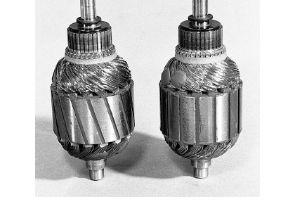
Fig. 1.12 Commutator rotor
It has a winding and a commutator configured with
multiple copper plates.
<1> In the case of DC, the stator flux is constant, but in the case of AC, it changes. Therefore, it is necessary to reduce any eddy current generated by the changing flux with insulated core lamination.
<2> Drops in voltage were only caused by resistance in the case of DC, but with AC, in addition to drops in voltage caused by resistance, output is also reduced by the deteriorated power factor due to the phase shift resulting from electromagnetic induction.
[3]-(2) Synchronous Motor
The synchronous motor refers to motors whose rotating speed is equal to the synchronous speed. They include the following three types:
[3]-(2)-<1> Reluctance Motor
The reluctance motor uses a stator of distributed winding (Fig. 1.13 Left) and a salient pole squirrel-cage rotor (Fig. 1.14 Right).
At the start, it rotates as an induction motor, and then rotates in sync with the power supply frequency while operating. Its rotating speed differs between 50 Hz and 60 Hz areas. This motor has a comparatively large startup torque. It is also called a reaction motor.
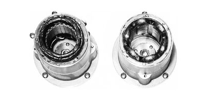
six-coil concentrated winding stator (Right)
(Right) Salient pole squirrel-cage rotor (for reluctance motor)
Copper, brass, and aluminum are used as conductors.
[3]-(2)-<2> Hysteresis Motor
Weak permanent magnet steel that does not
cause magnetization
The hysteresis motor uses a stator of distributed winding (Fig. 1.13 Left) and a semi-hard steel rotor (Fig. 1.15).
Since this motor rotates using the hysteresis characteristics, it has little rotational irregularities or vibrations. In addition, because there is no difference between the startup and stop torques, it should ideally be operated under a constant load condition. This motor can only be produced by manufacturers that have a special hysteresis ring.
[3]-(2)-<3> Inductor-type Motor
The principle of operation of inductor-type synchronous motors is synchronization of the rotor movement with the frequency of the current applied to the stator coil (electromagnet) and conversion of the input power into rotary motion through repeated attraction and repulsion.
In other words, the revolution speed of the rotor will be the inverse of the integer of the rotating speed (synchronous speed) determined uniquely by the frequency of the current. The motors can be classified into two types depending on the rotor structure.
- ・Claw-pole motors
- ・Hybrid stepping motors (slow-synchronous motors).
Claw-pole motors with various rated speeds are available by combining the motor structure and gear head.
Claw-pole motors are used in various applications including game machines (pinball machines), copy machines, security camera drivers, recording meters, automated curtains, and valve opening/closing devices. Hybrid stepping motors are mainly used for manufacturing machinery.
[3]-(3) Induction Motor
This is usually called an induction motor but it is occasionally called an asynchronous motor.
It is a generic name for motors whose rotating speed is slightly slower than the synchronous speed. The following three types exist. In either case, a stator of distributed winding (Fig. 1.13 Left) is used.
[3]-(3)-<1> Squirrel-cage Rotor Type Induction Motor
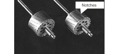
To the left is the rotor of a squirrel-cage rotor type
induction motor, and to the right is the rotor of a
reluctance motor.
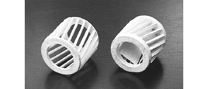
The squirrel-cage rotor (Fig. 1.14 Left) is used for the squirrel-cage rotor type induction motor.
General purpose power motors for industrial use are of this type. When a squirrel-cage rotor is dipped in nitric acid to dissolve the iron content, only the aluminum "cage" remains as shown in Fig. 1.16. It is possible to adjust the characteristic curve delicately by adjusting the shape and material of the cage-type conductor of the rotor.
[3]-(3)-<2> Eddy-current Motor
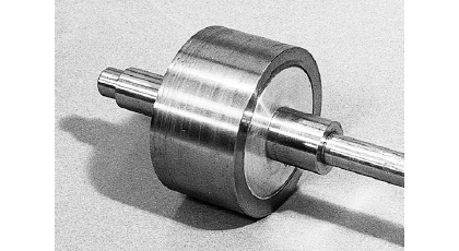
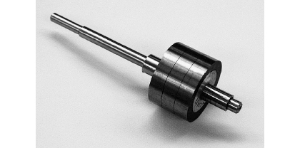
The main material is a cylindrical mass of iron.
For eddy-current motors
Soft-steel rotor (Fig. 1.17) is used for the rotors of eddy-current motors. It generates a large torque at the start of operation, which drops as the speed increases.
[3]-(3)-<3> Wound-rotor Type Induction Motor
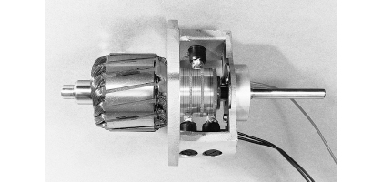
It is equipped with three slip rings to energize the rotor
with the brush.
Winding rotors (Fig. 1.18) are used in the wound-rotor type induction motors. The motor characteristics can be changed using a variable resistor connected through the slip rings. This rotor is specifically used in large motors.
[3]-(3)-<4> Single-phase Induction Motor
We have described multi-phase (three-phase) induction motors in <1> through <3> above.
In our daily lives, the power supply most people are familiar with is the single-phase AC power supply. Therefore, practical motors that operate on single-phase alternating current would be convenient. The single-phase induction motor meets this requirement. Small motors of this type, with an output range of several Watts to several hundred Watts, are widely used in household, small-scale industrial, and agricultural applications. Capacitor motors and shaded-pole type single-phase induction motors are typical single-phase induction motors.
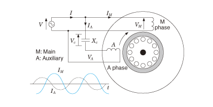
[3]-(3)-<4>-a) Capacitor Motor
capacitor motor
use
As Fig. 1.19 shows, capacitor motors are configured by inserting a capacitor into the A-phase so that VA becomes a leading phase to VM.
Capacitor motors are classified into capacitor-starting motors where capacitor C is inserted only at startup, capacitor run motors where constant capacitor C is kept inserted from the startup time onward, and binary capacitor motors that reduce the capacitance by switching the capacitor when the motor enters a steady operation status.
Besides being used preferably in home appliances that have comparatively smaller starting torques, in industry, the capacitor motor is used in small belt conveyor drivers and FA (factory automation) machines due to its ease of use and high cost effectiveness.
[3]-(3)-<4>-b) Shaded-pole Type Single-phase Induction Motor
The shaded-pole type single-phase induction motor is an induction motor that has a short-circuited auxiliary winding located at a position shifted from the master winding by an electric angle of less than 90°.
The auxiliary winding induces voltage using the transformer effect of the master winding to apply short-circuited current, and generates a rotating magnetic field using the magnetomotive force of the auxiliary and master windings.
Being less efficient due to the loss generated on the shaded coil, this motor is used in the fan and other small capacity appliances due to its simple structure.
Synchronous and asynchronous
In discussions of rotating magnetic field-type motors, the words synchronous and asynchronous are often used. These terms are associated with the engineering factor of "whether or not the motor rotates in sync with the frequency of alternating current". The following are important terminology:
◎Synchronous speed N0
Synchronous speed is a significant parameter used in relation to rotating magnetic field-type AC motors. It is determined by the frequency and the number of magnetic poles.
Motors rotating at a synchronous speed are called synchronous motors.
Motors that rotate slower than the synchronous speed are called asynchronous motors.