Quest For Motors' Hidden Abilities and New Potentials
Lecture 9: Compact Motors that Utilize Neodymium Magnets and Their Increase in Torque
In this volume, I shall examine some aspects of the recent design trends in compact motors while reviewing my earlier articles. In doing so, it is my hope that the reader will come to realize the meaning of the trend to use powerful neodymium magnets to generate high torque in a compact motor.
◇ Reviewing Tesla's original conception
As I wrote in Vol. 1, Tesla conceived the alternating-current induction motor when he was watching the sunset in a park in Budapest. Its winding was something like that shown in Fig. 1-2. It is called a concentrated winding, where a single coil is wound on a single tooth of the core. This is the topic of this installment. The majority of industrial motors are induction motors, which employ distributed windings, as shown in Fig. 1-4, instead of concentrated windings. Today's DC motors are drum motors, which I noted in a column in Vol. 1; they too employ a type of distributed winding. What is a distributed winding? We shall make use of q, which denotes the number of teeth per pole per phase, to answer this question.
q = number of teeth of the core ÷(number of poles × number of phases) (1)
A few examples are presented in Table 1.
| Vol.-Fig. no. | Number of teeth |
Number of magnetic poles |
Number of phases |
q | Application |
| 1 - 2 | 4 | 2 | 2 | 1 | Tesla's invention |
| 1 - 4 | 24 | 4 | 3 | 2 | Instructional |
| 5-Table 1 | 9 | 8 | 3 | 3/8 | Industrial robot |
| 5 - 4 | 12 | 4 | 3 | 1 | Competition-grade model airplane |
| 4 - 4 | 120 | 60 | 2 | 1 | Inertial navigation system for aircraft |
| 9 - 1 | 6 | 4 | 3 | 1/2 | Instructional |
| 9 - 1 | 6 | 8 | 3 | 1/4 | Instructional |
| 9 - 4 | 24 | 32 | 3 | 1/4 | Drone |
When q is two or greater, we have a distributed winding. In Fig. 1-2, there are two sets of coils, A and B. This is called a two-phase winding. The overwhelming majority of today's AC and brushless motors are three-phase motors. The hysteresis motor described in Vol. 2 must have a distributed winding to run. The early brushless motors, depicted in Fig. 2-3 and Fig. 7-3, also have distributed windings.
When q is less than one, we have a concentrated winding. The two windings shown in Vol. 4 (Figs. 2 and 4) are concentrated windings.
q = 1 represents the dividing point between concentrated and distributed windings. Here, I wish to bring the reader's attention to the complex winding shown in Fig. 4-4. It introduces novel Y-shaped teeth into Tesla's original arrangement. There are two phases, in one of which each coil spans two teeth. By arranging coils in this manner, where individual coils are used for two phases, the induction motor's performance can be improved. At the end of this volume, I present a short biography about Colin McDermott, who invented this motor for an inertial guidance system, which enables an aircraft to determine its self position and orientation.
The motor shown in Fig. 5-4, a typical example in which q = 1, is a compact, powerful motor used to drive the propellers of a model airplane.
◇ What do the number of magnetic poles indicate?
When current is passed through the motor, the coils for each phase generate magnetic poles in the manner NSNS. In the distributed winding, two or more coils are used to generate a single magnetic pole, so as to generate a smooth magnetic field that resembles a sine wave. This is the meaning of "q = 2 or greater." This suggests that the number of magnetic poles is determined by the coil connection. With concentrated windings, however, the number of magnetic poles is unrelated to this basic concept and instead determined by the number of poles of the rotor's permanent magnets.
◇ Six-tooth concentrated winding
Figure 9-1 is presented to examine the six-tooth winding that was shown in Fig. 4‐2 in Vol. 4. It shows there can be two, four, or eight magnetic poles. A six-pole rotor cannot be used for a motor.
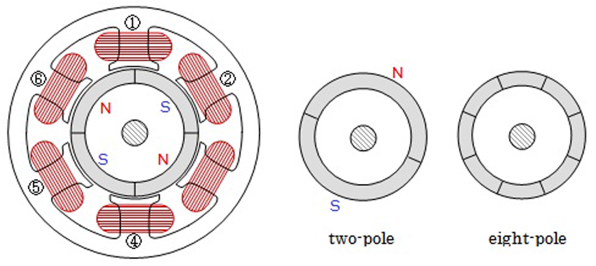
or adjacent ones (1 and 2). The paired coils can be connected to have
the same polarity (NN or SS) or opposite polarities (N and S).
to form a brushless motor, there are many ways of combining and connecting
the six coils. The number of the rotor's magnetic polarity can be 2, 4, or 8.
In practice, eight magnetic poles are frequently used.
The figure also shows that there are many ways of connecting six coils. Figure 9-2 shows the arrangement of the winding, magnets, and Hall IC (= integrated circuit element) in an outer-rotor motor.
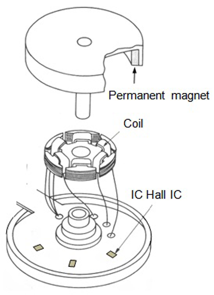
The mechanism to determine the coils to be excited and their polarity
based on this information is built into an electronic circuit.
When training a motor scientist or engineer, it is important to bring up the question "why?" One must be able to form a clear picture in one's mind, in terms of electrodynamics, of why a motor of a certain construction will run, why almost all brushless motors today adopt concentrated windings, or why the current trend is to use permanent magnets with a higher number of magnetic poles. None of these questions can be satisfactorily answered in the space of a few pages.
It was Teare, who was discussed in Vol. 2, who derived the following expression for the torque generated by a motor that employs permanent magnets.
Those interested in the details or the meaning of the integral are referred to reference [1]. Teare proposed this expression as the torque generated by the magnetic hysteresis occurring in a weak permanent magnet material. Did Teare realize that this is a basic expression that can also be applied to the brushless motor, which employs permanent magnets, to determine the current limit above which the magnet becomes irreversibly demagnetized? Based on this expression, this writer derived an expression that gives a rough estimate of the maximum torque, expressed as the product of the number of magnet pole pairs (one-half of the number of magnetic poles, p), magnet volume, and maximum energy product (BH)MAX, as follows:
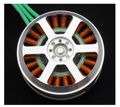
◇ Motor for transport drone: design to generate large torque with a small motor
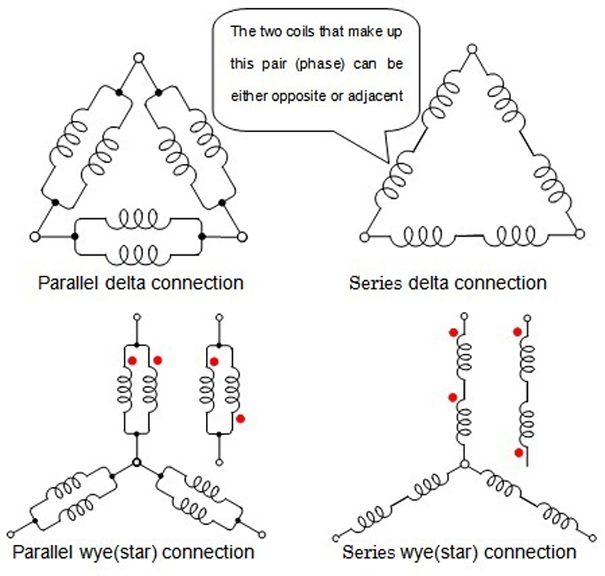
there are about 100 possible connection configurations of the stator winding.
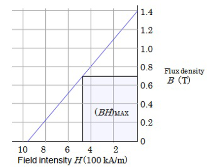
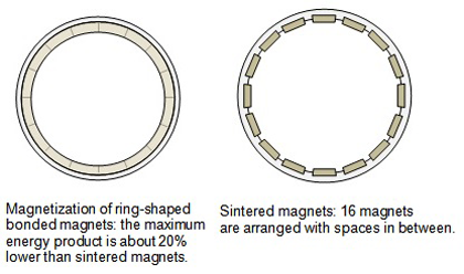
product of sintered neodymium magnet; (BH)MAX=336kJ/m3
Figure 9-5 shows a 90mm-diameter 32-pole motor, developed for use in transport drones. The theoretical maximum torque is about 30Nm. Expression (2) does not contain any parameters related to the winding, suggesting that it is up to the design engineer to adopt a winding design that achieves the theoretical torque limit. If we employ a distributed winding, the number of teeth or slots is 96 for q = 1, or 192 for q = 2; since these configurations are difficult to achieve in practice, the actual motor adopts q=1/4, with a 24-tooth core. Although a regular winding is used in this motor, measures to reduce the Joule heat generated in the winding constitute a leading-edge technology.
An inner-rotor construction can be adopted for high-power motors to achieve sufficient mechanical strength, an example of which is shown in Fig.9-6(a). The cross-section shown in (b) is used to ensure sufficient magnet volume in a multi-pole configuration within a small rotor volume. Incidentally, this motor configuration reminds me of multicylinder gasoline engines used in propeller-driven aircraft of the past.
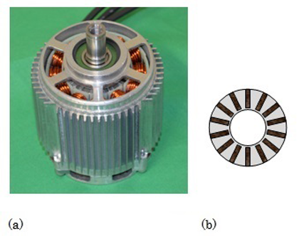
(b) its rotor cross-section (arrangement of mild steel and magnet segments)
The following link (in Japanese) gives a brief description of NIDEC's involvement in the development of drone motors: http://www.nidec.com/brand/tech/drone/index.html
Reference
[1] B.R.Teare, Jr: Theory of hysteresis motor torque, AIEE Transactions, Vol 59, pp 907-912
(1927-19 February 2014)
After spending an idyllic childhood for five years in West Yorkshire, his family moved to a town where Colin entered primary school. But the change from rural freedom to regimented classrooms full of germ-laden pupils laid him low with a variety of childhood diseases which left him with damaged lungs and a constant flow of respiratory diseases. He spent much time away from school. But, thanks to a twelve-volume encyclopaedia his parents bought for him, he was able to satisfy the entry requirements for Grammar School. He displayed talent in violin but gave up his hope to become a professional musician for financial reasons.
After a series of failures he was accepted by Manchester University College of Technology for a degree course. Manchester was and is a very musical town. He found himself running a big lunchtime concert involving the combined college choir with instrumentalists gathered from the two music colleges.
After graduation he obtained a post of researcher at Bristol University for a two-year junior Fellowship. He joined in a project to make a normal induction-motor winding run at two different speeds.
In 1957 he was invited to join the research team in electromechanical devices at Ferranti Limited in Edinburgh and assigned the task of designing a new induction torque motor. Ferranti was employing 20,000 in Scotland during its peak years. In his words, "My chief engineer was interested in pioneering the design of an inertial navigator destined primarily for the new Concord Airliner but with other and mainly military applications in mind. ... The design objective was to select the optimum number of poles and design the windings and a laminated stack to occupy minimum axial length [in a flat-type squirrel-cage induction motor to be operated at 400 Hz]. There was a design aim of motor torque power per watt efficiency which was crucial to the success of the entire project. ...After a number of design and build tests on different pole numbers had been undertaken there came a crucial day when this feature had to be measured [which demonstrated that the target efficiency had been successfully acheived].." The selection of materials and manufacturing methods was also an important task.
For the creation of such a motor and navigation system the team leader must have the talent to recruit people with the needed skills and train and organize them. McDermott must have acquired this skill through the orchestra activities during his college years.
In the late 1970s when he was creating a technology transfer team for the US Navy he was busy as Secretary of the Edinburgh Playhouse Society as well. Through this saving/renewal activity of the multi-purpose theatre he had friendly contact with Edward Heath, a conductor who had also been Prime Minister of the UK (1970-1975). Since retirement from Ferranti in 1989,McDermott dedicated his life to musical activities.
Reference:
[http://www.edinburghnews.scotsman.com/news/obituary-colin-mcdermott-playhouse-campaigner-85-1-3335762]