1-3-5. Stepping Motor
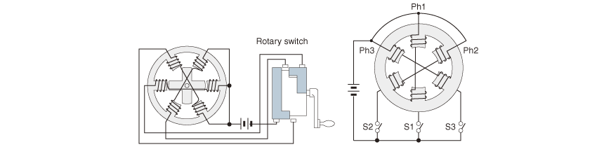
The original form of the stepping motor is a combination of a six-coil concentrated winding stator (Fig. 1.21) and a salient-poled lamination rotor (Fig. 1.22). It was adopted as the actuator for indicating the launching directions of torpedoes from British navy warships during the 1920s as shown in Fig.1.23.
A rotary switch was used in this motor for switching the current between the windings.
Functions of these switches are indicated by S1, S2, and S3 on the right-hand side in Fig. 1.23.
The stepping motor was once called a step-by-step motor. However, before long it became more popularly known as a stepping motor or step motor.
It is also called a stepper motor.
Fig. 1.24 shows that the rotor position rotates in step with the switching of the current to the stator winding.

[5]-(1) VR Stepping Motor
The rotor of a stepping motor is required to hold its position upon stopping after rotating by a certain number of degrees.
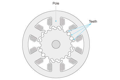
To achieve this, a principle is applied in which the poles (large teeth or pole teeth) excited by electric current are arranged by the rotor teeth and magnetic force.
In cases where the ratio of the number of stator gear teeth to that of the rotor gear teeth is 6:4, the positioning resolution under this principle will be 12 per rotation. In other words, positioning can be made at intervals of 30 degrees.
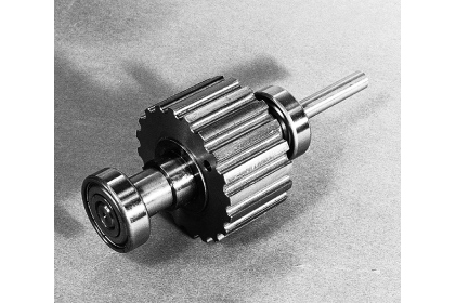
As a means of creating high resolution, a pole with fine-notched teeth as shown in Fig. 1.25 and a rotor with similarly fine teeth as shown in Fig. 1.26 are used.
This type of stepping motor that does not use permanent magnets is called a VR (Variable Reluctance) stepping motor.
Looking back in history, various types of VR motors were manufactured for use in machine tools and computer device peripherals.
One of the advantages of the VR stepping motor is that it can create high resolution by machining fine teeth and reducing the size of the gap between the stator and rotor.
A disadvantage is that it is difficult to satisfy the needs for both downsizing and creating larger torque at the same time. For this reason, the VR type draws more attention today as an SRM (switched reluctance motor), which is a kind of brushless motor, rather than as a stepping motor.
by adding notched teeth to the pole
Configuring VR stepping motor
[5]-(2) PM Stepping Motor
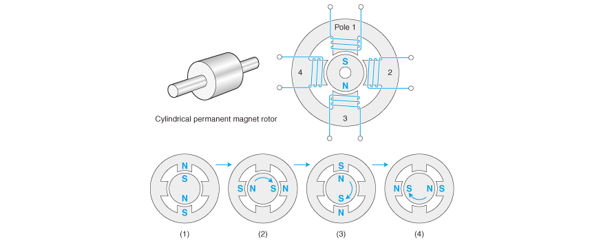
Separate from the VR type, the PM (Permanent Magnet) stepping motor was developed. Basically, this motor used a permanent-magnet rotor as shown in Fig. 1.27. For a typical example, a combination of a four-coil stator and a bipolar magnet rotor as shown in Fig. 1.28 can be mentioned. This motor evolved in the field of stepping motors used in wristwatches. One characteristic of these stepping motors is that they have a low level of power consumption if they are made more compact due to the powerful permanent magnets they contain. A single battery can keep driving the three hands, including the second pointer, for several years.

[5]-(3) Hybrid Stepping Motor
Today's hybrid stepping motors, which have a wide range of applications, are a compound type that combines the advantages of both VR and PM types. Production is concentrated on the so-called claw pole type, but in a wider sense it is regarded as one of the hybrid stepping motors.
Originally, "hybrid" is a biological term. Here, hybrid refers to the VR structure that has a finely notched stepping angle, and its use of permanent magnets increases torque.
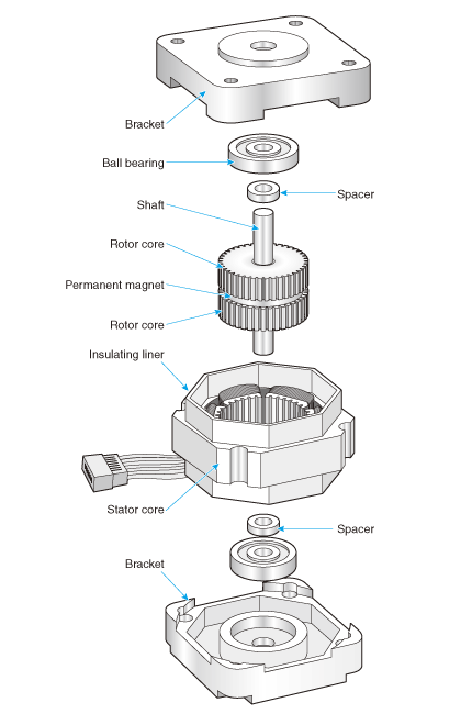
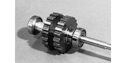
Its construction is shown in Fig. 1.29. Basically speaking, as seen in the rotor structure in Fig. 1.30, two strips of the tooth-notched core sandwich the disc, which is a permanent magnet.
Fig 1.30 Inductor rotor
A ferrite permanent magnet is sandwiched between two strips of tooth-notched core. One side of this magnet is the N-pole while the other side is the S-pole. Only one magnetic pole, N or S, appears in the section vertical in the axial direction. This is a unipolar. Since a magnetic pole is induced in the teeth of the silicon steel on both sides, they are called inductors. When viewed from an axial direction, it looks like a multipolar permanent-magnet rotor. It is used in a hybrid stepping motor.
[5]-(4) Claw-pole PM Stepping Motor
The stepping motor used in a wide range of office equipment is this claw-pole PM stepping motor.