Product Information
FA system products
I explain about NIDEC INSTRUMENTS's FA system products.
NIDEC INSTRUMENTS provides FA automation systems in addition to FPD transfer robots and semiconductor wafer transfer robots.
We provide loader/unloader and in-line system of CF, PI process and ODF process with our FPD transfer robots.
In the field of post-processing of FPD manufacturing, we provide an automated inspection system that automatically turns on and performs automatic inspection for FPD modules of various shapes.
M-CONTactTM series.
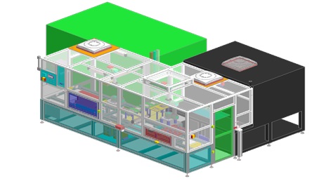
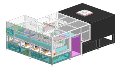
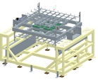
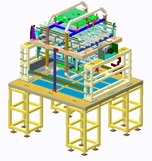
FPD module automatic lighting inspection device and peripheral equipment
FPD module automatic lighting inspection device
Since the post-process of FPD has a variety of production varieties and it is very difficult to standardize the process, there is still a lot of work done by human hands.
To solve this problem, NIDEC INSTRUMENTS is helping automate by developing a lighting inspection device ”M-CONTactTM”series that enables automatic contact with the signal interface, an essential function to automatically check the operation of modules
that are close to completion in the production process.
Basic concept of M-CONTactTM
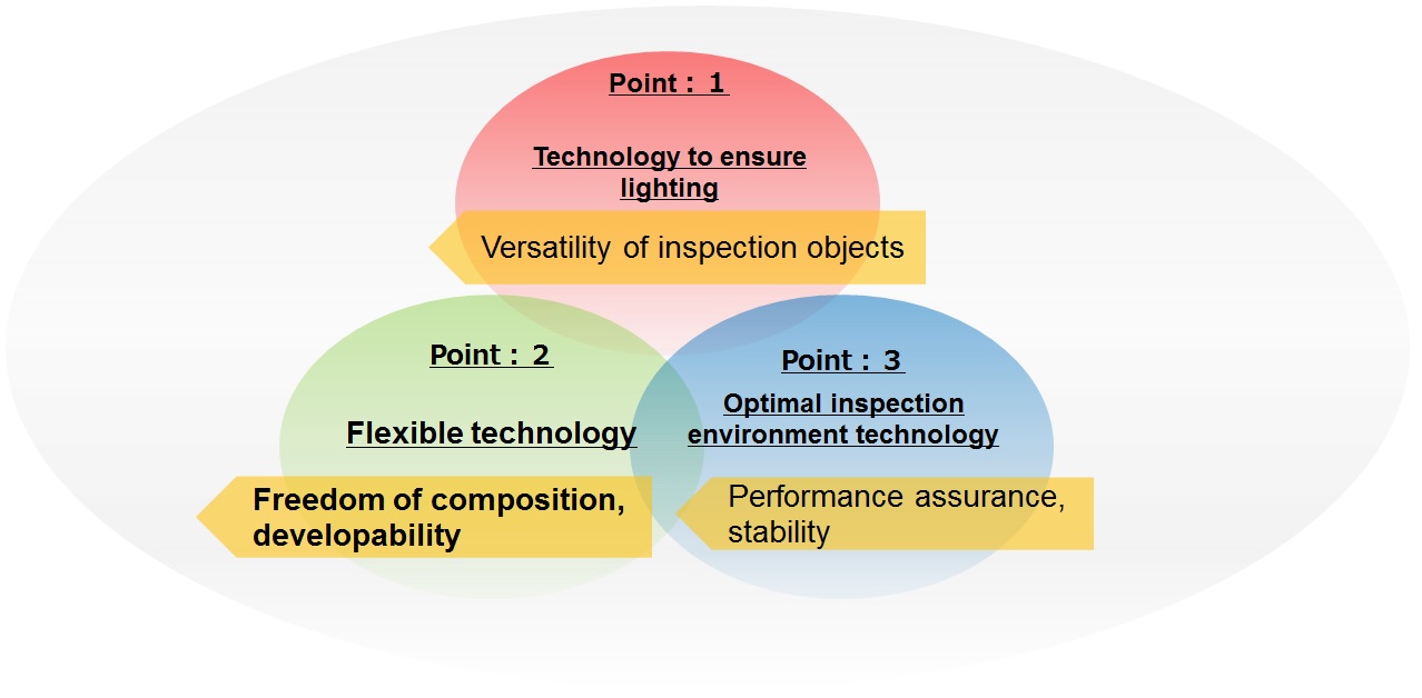
"Are you having trouble with a panel that does not light up? We will solve it with technology to ensure that it lights up."
Technology to ensure lighting
The system is equipped with an image processing contact unit that can be adapted to a wide range of product shapes, structures and interfaces. This ensures a reliable automatic lighting inspection.
Please contact us if you have any questions about the automatic contacting of FPCs, connectors, etc.
"With the concept of freedom and development, we are able to automate high-mix low-volume production, save manpower and improve installation space efficiency."
Flexible technology
In order to cope with high-mix, low-volume production, we have minimized the number of jigs and fixtures to reduce set-up times.
The jigs can be manufactured by the customer by means of design standardization. We can also convert your existing jigs to the new system on request.
We can flexibly adapt the layout of the machine to suit your needs by reducing the size of the machine.
The lighting process including inspection is also available as an option. Unevenness inspection, brightness chromaticity measurement, OTP, etc.
"Do you have a problem with false positives? We can provide you with the optimum testing environment for your testing needs."
"Optimal inspection environment technology"
The equipment is equipped with a thorough darkroom environment, optical environment and adjustment mechanisms for optimal image processing.
It is designed to prevent over-detection due to foreign objects, scratches or other factors. The system is also designed to prevent vibration during imaging.
Automatic contact technology
NIDEC INSTRUMENTS has a "technology to make sure lighting" that is important as a technology necessary for lighting inspection.
With its original automatic transfer technology and image processing, it is possible to delicately handle connector cables of various shapes, recognize their positions with certainty, and make sure to contact probe units to communicate signals.
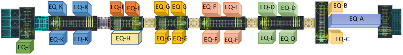
Examples of corresponding modules


Product line
M-CONTactTMseries
FPD module automatic lighting inspection device
Method of model display
| Type | - | PK | - | 1 | - | C120 |
| : | : | : | ||||
| Type | Model name | Number of sheets processed | Camera specifications | |||
| Type | PK:Panel Inspection MH:Module-OPEN MT:Module-CLOSE HT:Module-OPEN_CLOSE |
1:1 sheet inspection (8 to 15.6 inches) 2:2 sheets inspection (1.5-7 inches) |
C120:120M Camera C151:151M Camera C250:250M Camera |
|||
| Series | Specifications | Product data |
| Type-PK-1-C | Panel Inspection 1 Camera | ▼ |
| Type-PK-2-C | Panel Inspection 2 Camera | ▼ |
| Type-MH-1-C | Module-OPEN Inspection 1 Camera | ▼ |
| Type-MH-2-C | Module-OPEN Inspection 2 Camera | ▼ |
| Type-MT-2-C | Module-CLOSE Inspection 2 Camera | ▼ |
| Type-HT-2-C | Module-OPEN_CLOSE Inspection 2 Camera | ▼ |
FPD Module peripheral equipment
| Series | Specifications | Product data |
| Loader unloader | Tray stacking, tray disassembly, supply and discharge | ▼ |
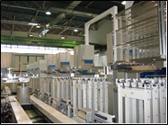
Loader / Unloader for FPD manufacturing equipment and transfer system
Loader / Unloader system
We provide Loader / Unloader systems using our FPD transfer robot.
We have the delivery record of indexers and in-line systems in ARRAY, CF, and CELL processes at FPD manufacturing plants.
In each process, units such as cassette stage, glass alignment, turn, and turnover which flips the board upside down are required, and a line is constructed including a dedicated unit as needed.
Reference example CELL ODF Process
(after VALC)
-
Loader/Unloader device using 8th generation robot
-
Panel supply system by combining wire cassette + conveyor robot + transfer robot
"We propose the construction of an in-line system with an optimal layout using own large LCD glass substrate transfer robot"
Our large LCD glass substrate transfer robot has the rigidity for large substrate transfer, and can operate at high speed by reducing the weight of the robot body and increasing the power of the motor.
The HAND is made of carbon fiber reinforced plastic (CFRP) with a hollow structure inside the fork and a double tapered structure at the fork tip in the width and height directions to reduce weight.
CFRP is a material whose rigidity varies according to the direction and shape of its fibers, and can be made lighter and more rigid by combining the shape and fiber direction.
The use of CFRP hands enables high speed, high precision and low vibration transport.
The cleanliness of the robot is explained below.
The inside of the robot cover contains timing belts, ball screws and linear guides, which are the source of dust, but instead of using exhaust ducts to suck the dust out of the enclosure, a filter unit with a fan is installed close to the dust point to create sufficient negative pressure to exhaust the dust.
The bearings used in the arm have a contact seal and a labyrinth structure.
The robot arms are not arranged horizontally, but are stacked on top of each other on a pillar axis.
Compared to a horizontal arrangement, this arrangement requires a turning radius of only one arm, thus reducing the footprint.
However, when the arms are arranged vertically, particles from the moving parts of the upper arm can contaminate the glass substrate on the lower arm.
We have used our years of experience and expertise in cleanliness technology to achieve a high level of dust resistance, and have succeeded in adopting a top and bottom arm arrangement that no other company has achieved.
The basic concept of our robots is to save energy, and the mechanical structure does not depend on motor power. In the case of Z-axis robots with a flexure-type structure, the load on the motor changes according to the position.
Although there is no change in power consumption during operation, in the case of robots used in the liquid crystal manufacturing process, the upper and lower axes are stopped for 60% of the operating time of one cycle, so the size of the motor becomes larger due to the need to maintain the posture of the flexure type.
We use linear motion axes for the upper and lower axes, where the load on the motor shaft does not vary with the posture, to save power. For maintenance, the mechanical parts are gathered in a position where maintenance can be carried out at a low position, eliminating the need for work at height as much as possible.
The reduction gears and servomotors of the drive unit are made as a unit product, which eliminates the need for adjustment during replacement and improves maintainability.
The use of a highly reliable general purpose controller and the common use of maintenance parts ensures the fastest possible support.
The robot controller is based on modern control theory and uses low dimensional robust pole positioning control technology to ensure low vibration, high precision drive, high repeatability and stability."
In order to cope with the large size of the glass substrate, the control functions include a smooth stop function and an operation area limit function to ensure safety.
On the hardware side of the controller, safety functions have been strengthened (smooth stop function during EMO and EMS, double emergency stop, emergency stop switch failure detection, brake circuit failure detection, etc.), field bus functions have been expanded, and memory capacity has been increased significantly.
This is the description of the robot used in our system.
While using this robot, we can provide the most suitable inline equipment in a way that meets the customer's requirements by means of various peripheral equipment units and control system proposals.
"We carry out desktop simulations of 3D virtual robots and propose the best layout for the required tact time."
The 3D Analyzer simulates the behavior of a virtual robot instead of a real one, using only a controller. It is not just a command level simulation, but also a simulation of the simple dynamics of the robot. By using the parameter files of the real robot, it is possible to simulate the robot as defined in the parameter files. By simply changing the parameter file (HWDEF file) for each model, the robot can be used with various types of robots. The teaching pendant can be operated in the same way as on the actual robot. It is also possible to monitor the coordinates of each axis, JOG operation, teaching operation, etc. 3D animation of virtual robot motion can be displayed on a PC and viewed from various angles. The robot program developed for the final product can also be used for control from the PLC. This has greatly improved our development efficiency. It is a very effective tool for tact verification before introducing a robot, as there is almost no time error with the actual machine. By using this simulation from the specification stage, it is possible to establish the optimum line. It is also possible to acquire movement data from a robot already in operation and use this data to replay the movement on a PC. Together with the movement waveform, this allows us to verify wasted waiting time and our specific overlap optimization.
"Simulation of glass substrate deflection to calculate optimum handling conditions and help to determine equipment and robot arrangements."
In order to simulate the condition of glass on a robot hand or in a storage area and to calculate the optimum handling conditions, shell elements can be used in the general-purpose FEM software ANSYS. By modelling how much the glass deflects under its own weight when it is placed on several support materials, and by varying the glass shape and material properties, and applying a gravitational acceleration to the entire glass, the deformation and stress due to deflection can be calculated. It can be used to design the hand (end-effector) of a transfer robot and to check the fit of the robot's access device.
"We propose the construction of a total automation system based on IoT."
We propose the construction of a total automation system, using a network of process information such as equipment operation status monitoring and CIM data. The existing function of sending process information from the CIMPC to the host is retained. On top of that, we can provide additional functions to connect monitoring cameras, electrostatic monitors and other monitoring sensors and send the information to the host.
CIM correspondence
We offer a control system including in-line total information management by CIMPC, loader master and various CIM support for BC.
We also provide the interfaces between the machines to realize them.
Standard interface specifications CIM network example
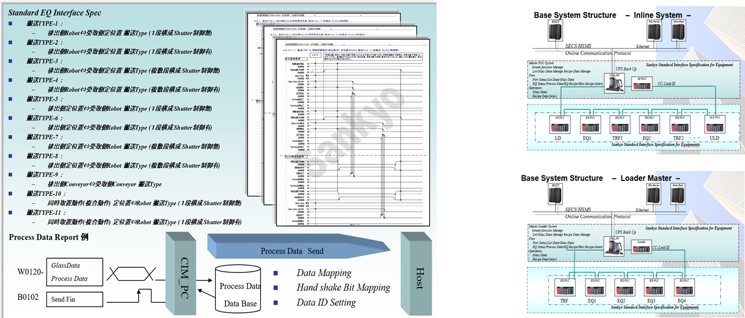
Example of flow for providing interface between devices
"We have a proven track record in providing inter-machine interface specifications, including inter-machine communication, information collection and management."
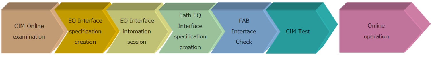
We can create inter-machine interface specifications to meet your information management needs, while using our standard specifications to build a network for each line.In addition to confirming hardware and software interfaces between equipment, and explaining common specifications to equipment manufacturers, we also hold meetings with equipment manufacturers to explain specifications for CIM information reporting. In individual meetings with equipment manufacturers, we provide specific interface specifications for special equipment.
"To ensure stable operation, we also check equipment interfaces at the FAB."
In accordance with the checklist, the interface of each piece of equipment is checked on site. Before the FAB test, it is also possible to perform a simulated interface check using a simulation environment. The FAB test can be used to summarize the operational status of the equipment and to test online communication with the host PC to ensure stable operation of the equipment.
"Providing an easy-to-understand man-machine interface."
The system provides a real-time visual representation of the equipment status. A wide range of logging functions, such as communication logs, signal change logs and error histories, contribute to trouble analysis. The log can be saved as a file and retrieved as required.
Inquiry on our products
NIDEC INSTRUMENTS CORPORATION
Contact Us
Contact Us by Phone
+81-266-27-3111
Reception hours: 8:30 AM to 5:30 PM (excluding Saturdays, Sundays, national holidays and our Company holidays)