Quest For Motors' Hidden Abilities and New Potentials
Lecture 2: Steinmetz and the Hysteresis Motor
Several amazing motors have been developed in recent times. Each was amazing in its own way.
One of them, the hysteresis motor, was very conveniently applied to tape recorders.
There is no question that tape recorders were important devices in terms of data recording, storage and reading to and from a magnetic medium (long magnetic tape). For analog signals, it is important that magnetic tape is fed at a constant speed. The hysteresis motor made this possible thanks to a very simple structure.
The hysteresis motor is an alternating current motor of the rotating magnetic field type as mentioned in the preceding article. It rotates at a constant speed related to the frequency of the AC power source. We call such a motor a synchronous motor.
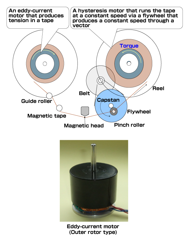
To start a medium or large orthodox synchronous motor from a standstill state, a separate starting component is required, something a hysteresis motor does not need. Simply applying an AC current to the winding causes the motor to start and accelerate smoothly and begin operating at a synchronous speed.
This amazing mechanism is created using the ring-shaped magnetic material shown in the photograph of Fig. 4 in the preceding article. Characteristics of the material enable the motor to start smoothly and accelerate until it reaches a synchronous speed where the motor runs at a constant speed irrespective of load variation. This is one of the features of hysteresis motors.
Fig. 1 shows how a hysteresis motor was used in high-end tape recorders during the 1960s. The two-pole winding mechanism used in Japan rotated approximately 50 or 60 times per second. That is, 50 rotations in Kanto, Tohoku and Hokkaido, and 60 in areas west of the Fuji River in Shizuoka Prefecture.
As this speed is too fast, motors using a four-pole mechanism that rotate 25 or 30 times per second were manufactured. An eight-pole winding mechanism, which rotate 12.5 or 15 times per second, are also commonly used.
Who Discovered The Principle behind The Hysteresis Motor?
Who discovered the principle behind this motor? I agree with the opinion that one of the discoverers was Steinmetz.
As I have described in the current historical column, Steinmetz escaped to Switzerland from the Bismarck regime in Germany. After mastering the required units at ETH (Federal Institute of Science and Technology, Zurich), he went to America to seek refuge, and before long his talent bloomed. Based on the theory of hysteresis loss that occurs in a transformer during power transmission, I think that he discovered that magnetic hysteresis not only causes power loss but also generates torque when applied to an alternating current motor.
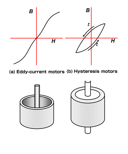
Magnetic hysteresis may be defined as the time relationships of B-H characteristics that draw a loop shown in Fig. 2(b). As shown in Fig. 2 (a), the magnetic steel, whose B-H characteristics vary on the curve or linear curve passing through the original point, is called soft magnetic material.
As Fig. 2 (b) shows, magnetic material whose current B-H state varies depending on the past state is called hard magnetic material. A permanent magnet is made of a hard magnetic material.
What is important to remember here is that it was James Ewing (1855-1935) who coined the word "hysteresis" upon discovering the hysteresis phenomenon in 1881 while staying in Japan. His discovery had a strong impact on British research into magnetism. At Cambridge University, researchers devoted themselves to promoting the electromagnetic theories of ferromagnetic substances. Livens was one of the people who took part in this research.
In one of his works written in 1918, the Theory of Electricity[1], he revealed a formula for electromagnetism that became the basis of the hysteresis motor, along with an abrupt addition of a theoretical expression of the electrostatic motor. He described these formulas by using the expression for vector analysis, which I feel somewhat lacks explanation.
I think the first hysteresis motor was manufactured in America 10 or more years after Steinmetz died (1923).
In 1937, B. R. Teare submitted to Yale University his dissertation, in which he developed the torque theory by applying the principle of virtual displacement to electrodynamics. He described data about production in detail.
For your information, seven years before Mr. Shigenobu Nagamori established Nidec (1966), he began studying designs for a motor for information-processing equipment at TEAC. He then surprised me by showing a copy of Teare's dissertation that he has obtained.
I don't know how he obtained it; perhaps he had a gift of attracting necessary things to himself!
In 1940, Teare contributed a paper about torque generated by a hysteresis motor based on a separate theoretical development to the journal of the then AIEE (American Institute of Electrical Engineers, now the IEEE)[2].
Pioneers of Japanese Tape Recorders Who Only Learned about Hysteresis Motor after The War
Let's take a look at the advances in physics in the world outside America where hysteresis motors were being manufactured.
In Europe, quantum mechanics underwent a major development. Heisenberg and Dirac caused great excitement among young physicists in Japan when they visited in 1929.
In 1935, Hideki Yukawa, then an Osaka University staff member, presented a theory advocating the presence of meson. His theory became a talked about topic among many specialists and he was invited to attend the Solvay Conference on Physics and subsequently visited Belgium in 1939.
However, the conference was canceled because of Hitler's invasion of Poland. For more details on the events during this time, please see the reference [3].
When the door to the theory of elementary particles was opened in the world of physics, an important motor for information-processing equipment was built in America that no Japanese engineers knew about. This is quite remarkable.
If compared with the advanced level of physics in Japan in the 1930s, which was already moved ahead of that in other countries, the researchers seem to have neglected theoretical studies of applied magnetic technologies even though they had invited a master in that field from Britain. It was only when American-made tape recorders were introduced to Japan after the end of the Second World War in 1945 that Japanese engineers first learnt about the hysteresis motor.
Since Japan had a patent for the alternating-current bias method that applied to magnetic recording, researchers believed they could establish a strong engineering capability by combining the patented technology with the hysteresis motor provided they could manufacture one by themselves. To do this, it was essential for them to attempt to develop a magnetic steel strip for the rotor.
When Hideki Yukawa was awarded the Nobel Prize in 1949, all Japanese were excited; however, Japanese researchers were not at that point able to develop a hysteresis motor for practical application. In the 1960s, Mr. Taku Yazaki of Tohoku Kinzoku developed an inexpensive magnetic steel strip exhibiting excellent characteristics with no dispersion.
The author himself received valuable help from Mr. Yazaki. Mr. Yazaki is a highly talented person who is now very active in the field of "haiku" composition.
Completion and Limit of Technology, and The Debut of Brushless Motors
If permitted to mention one small contribution I made to the field of hysteresis motors, it would be a practical method rather than a design theory of windings.
In Japan, AC power transmission differs according to frequency in two different areas in the country; one area uses 50 Hz and the other area uses 60 Hz. Consequently, motor rotating speed differs according to the frequency. Accordingly, I set up a mechanical method to provide a tape with different circumferential velocity, for example, 9.5 cm/sec for the four-pole winding or 4.75 cm/sec for an eight-pole winding by varying the outside diameter of the capstan.
However, optimum capacitance of the capacitors required to produce two-phase alternating current from single-phase largely depends on the frequency, Therefore, I set it, for example, to 3 μF in a 60 Hz area, and 4 μF in a 50 Hz area.
Under these conditions, my aim was to determine the specifications of the two sets of windings so that a four-pole winding and an eight-pole winding can be fitted into a given space. The author's method was first to conduct a basic measurement, then draw a diagram according to the data using a slide rule. Nowadays, a PC can complete such simple drawing in no time, but in those days my method was quite convenient.
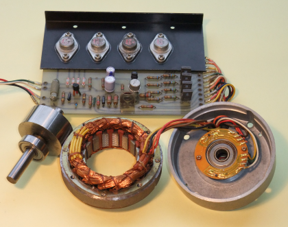
An alnico magnet was used for the rotor. For the stator, a coil with distributed winding is used, and a Hall element is used for detecting the rotor position. Four bipolar power transistors were used to produce two-phase alternating current from direct current.
The motor structure was almost the same as that of a hysteresis motor.
I think that Nidec should have used this design method during the company's foundation period.
This theory was completed during the 1964 Tokyo Olympics and presented in 1968. It was published in Technische Zeitschrift Aufgabe, a German scientific journal related to this field of engineering.
In those days, technological information in the field of compact precision motors was often learnt from literature written in German, and as a result I felt I could repay the help I received in a small way with my presentation. In retrospect, this was a way of adding a final touch to an already-established technique.
Before long, after a number of Japanese manufacturers of small motors launched production of hysteresis motors, brushless motors began to replace them.
If more parts were required, techniques were developed to create compact and precise speed control devices. The new technology helped to solve the complicated problem of the different frequencies (50 Hz and 60 Hz) once and for all.
Development of new technology is often accompanied with continuity, and this was also true in terms of the transition of hysteresis motors to brushless motors. Photograph of Fig. 3 shows brushless motors manufactured by Nidec during the 1970s.
Their structure is almost the same as that of a hysteresis motor. They only differ in the following three ways:
- 1) Material: Cobalt is added to the rotor ring material to transform it into a full-scale permanent magnet by enhancing its coercive force. This has made it possible to create greater output for the same size rotor ring. Alternatively, it can be made more compact for the same amount of output.
- 2) Adoption of inverter: An inverter produces alternating current at a desired frequency and voltage from direct current, and bipolar transistors are electronic devices that do such work.
- 3) Application of position sensing device: The control signal from the four transistors used for the inverter needs to be emitted by detecting the rotor rotating angle (position). In the example of Fig. 3, the rotor angle can be detected with the four poles and three units of the Hall element by dividing a rotation into 12 sections.
From Reproduction of Recorded Voice to That of Images
The limits of hysteresis motors became apparent when analog data recording/reproduction using magnetic tape progressed from voice to images.
Magnetic recording was digitalized and the media turned into hard disks. The hard disk is now driven by brushless motors using powerful permanent magnets.
Connection between Magnetic Hysteresis and Modern Technologies
I think what Steinmetz chose as his research subject was the influence of magnetic hysteresis on the transformer and large generators. This is still an important problem today.
Magnetic hysteresis generates heat (that is, it turns generated power into wasteful heat) and simultaneously generates torque as well. In the case of the basic rotating magnetic field-type motor model, the relationship between the loss and torque is well understood. However, with regard to an SR motor (switched reluctance motor) being noted as the energy-saving motor, a theory concerning this relationship is yet to be fully established. Therefore, commercial design software is not capable of calculating the correct loss and torque generation.
To implement development and design of motors that exhibit superb functionality, it is critical that researchers possess knowledge attained from basic in-depth research, accumulated data on material characteristics, and actual measurements. This is an area where potential issues requiring in-depth research into electromagnetism wait to be solved.
In the author's latest work, the "SR Motor"[4], I used a considerable number of pages to discuss issues related to studying the above-mentioned research subject.
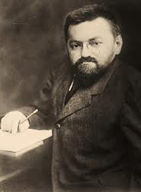
Steinmetz's father was a lithographic engineer for a railway in Breslau in southern Germany. In 1883, Steinmetz enrolled his son Karl (English name: Charles) at Breslau University hoping to find a way to make good use of his mathematical talent. At the university, Karl engaged in comprehensive studies. Immediately before graduating in 1888, he was almost arrested for writing an article criticizing the government led by Bismarck, the Iron Chancellor. Knowing the risk, he escaped to Switzerland via Vienna. He then entered ETH (now the Federal Institute of Science and Technology) and qualified to graduate by studying mathematics and mechanical engineering.
In 1889, he immigrated to America with a friend. It is said that it took him some time to enter America as he was penniless, unable to speak English, and because of his heredity-related physical features.
He started working in New York as a draftsman, simultaneously studying magnetic hysteresis. As he picked up English, Steinmetz joined the American Institute of Electrical Engineers (AIEE). His mathematical abilities that enabled him to design non-overheating motors based on accurate calculations of hysteresis became noted among the Institute members (he was 27 at the time).
In 1893 when the factory he worked for was affiliated with General Electric (GE), he worked under Edison. Rapid development of high-voltage AC transmission technology in America is owed to Steinmetz's brain power. Due to his outstanding and accurate calculating abilities, GE executives began referring to him as "Supreme Court".
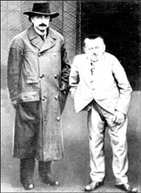
He presented his theory of alternating circuits using complex numbers in 1893 at about the same time as Arthur E., Kennelly (1861-1939) who was Edison's laboratory assistant.
Incidentally, this theory is an important tool used in electrical engineering. Steinmetz's AC circuit theory was also applied to the aforementioned design method of winding for hysteresis motors. Refer to the author (Kenjo)'s work[5] for descriptions of calculation methods using complex numbers.
The author once visited ETH. To my surprise, the training site used for measuring motors was beautifully laid out over a vast area of the premises.
For motor manufacturers, it is important to build workshops where practical on-the-job engineer training can be carried out efficiently and where technicians can be responsible for maintenance and control of motors.
As ETH provided business-related education (vocational training), it is surprising how it was able to help Steinmetz and Einstein nurture their innovative abilities.
- [1] G.H.Livens: The Theory of Electricity, Cambridge University Press, 1918
- [2] B. R. Teare, Jr: Theory of Hysteresis Motor Torque, Trans. AIEE 59, p.907 (1940)
- [3] http://gihyo.jp/science/serial/01/pythagoras/0014
Extra classes for more in-depth reading of "Understanding the Theory of Relativity with Pythagorean Proposition" (published by Gijutsu-Hyohron) authored by Kenjo and Sano; 14th lecture: Evolution from the theory of relativity to quantum mechanics and the Japanese era. - [4] Takashi Kenjo: SR Motor, (Nikkan Kogyo Shimbun)
- [5] Takashi Kenjo: Introduction to Electrical Engineering (Dempa Shimbunsha)

