Precision position detectors MP SCALE|Linear position detector|General of linear position detector
General of linear position detector
The handling companies : Nidec Machine Tool Corporation
- Contact information for product inquiry
- Contact Us
- Contact
- Environmental conditions
- Purpose and selection
- Mounting position
- Example of mounting
- Details of mounting design
- Pitch adjustment
- Accuracy measurement
Environmental conditions
The environmental conditions of Linear MP Scale are as follows.
| Items | Conditions |
|---|---|
| Ambient temperature | -10 to 70 deg. |
| Relative humidity | Less than 95% |
| Vibration resistance | Displacement amplitude 1.5mm, 10 to 55Hz |
| Impact resistance | 55G 11msec |
| IP code | IP67 Equivalent |
| Proof of coolant water, coolant oil and dew condensation | Although it does not consider using MP scale in the situation of immersed in those, if immersed at short time, the function of Scale operates without problem.However, if they are poured for a long time, the rust may occur on Scale blank, and fault may occur. |
| Foreign material | If aluminum foil is not striped or the pattern is not injured even if the foreign materials enter between Rotor and Stator, Scale operates without problem. However, since cutting chip becomes the factor which gives the crack, please protect with the cover etc. |
Purpose and Selection of Linear MP SCALE
For small machine, MPLN series nallow-type Linear MP SCALE
Features
Get high accuracy by mounting MP Scale at best position, as it is thin and narrow.
Space saving with built-in preamplifier
Note)This scale is not connectable for long stroke.
| Stroke | MPLN Series | Scale length |
|---|---|---|
| 175mm | MPLN-25ASC | 252mm |
| 245mm | MPLN-32ASC | 322mm |
| 375mm | MPLN-45ASC | 452mm |
| 545mm | MPLN-62ASC | 622mm |
For general machine, MPLZ series absolute Linear MP SCALE
Features
High accuracy 5μm/1m
Space saving by built-in preamplifier
Connectable with various NC system
Note)This scale is not connectable for long stroke.
| Stroke | MPLZ Series | Scale length |
|---|---|---|
| 150mm | MPLZ-25BSC | 252mm |
| 400mm | MPLZ-50BSC | 502mm |
| 650mm | MPLZ-75BSC | 752mm |
| 776mm | MPLZ-87BSC | 878mm |
| 900mm | MPLZ-100BSC | 1002mm |
| 1150mm | MPLZ-125BSC | 1252mm |
| 1400mm | MPLZ-150BSC | 1502mm |
| 1650mm | MPLZ-175BSC | 1752mm |
| 1900mm | MPLZ-200BSC | 2002mm |

For general machine MPLC series (Standard incremental type)
Features
High accuracy 5μm/1m
Space saving by built-in preamplifier.
Absolute detection is possible, combining the battery back-up encoder on feed motor. ( In case of FANUC and MITSUBISHI CNC )
Note)This scale is not connectable for long stroke.
| Stroke | MPLC Series | Scale length |
|---|---|---|
| 150mm | MPLC-25BSC | 252mm |
| 276mm | MPLC-37BSC | 378mm |
| 400mm | MPLC-50BSC | 502mm |
| 526mm | MPLC-62BSC | 628mm |
| 650mm | MPLC-75BSC | 752mm |
| 776mm | MPLC-87BSC | 878mm |
| 900mm | MPLC-100BSC | 1002mm |
| 1026mm | MPLC-112BSC | 1128mm |
| 1150mm | MPLC-125BSC | 1252mm |
For large machine, MPS-C series connectable-type Linear MP SCALE
Features
High accuracy 5μm/1m
Long stroke is possible by connecting up to 35m.
Stroke
| MPS-C Series | Scale length |
|---|---|
| MPS-25CSC | 250mm |
| MPS-50CSC | 500mm |
| MPS-75CSC | 750mm |
| MPS-100CSC | 1000mm |
Scale length and Stroke
The stroke is value which subtracted 100mm from the sum total of the length of selected Scales.
Ex) When MPS-100CSC are 3 pieces and MPS-75CSC is 1 piece,Scale stroke is,
1000mm×3 pieces+750mm-100mm=3650mm
Note) Preamplifier is required.
Mounting position of a Linear MP Scale
We recommend not mounting Linear MP Scale by addition after the machine has been manufactured, but considering mounting of MP Scale and securing the mounting space at the design time. And also, we recommend directing that the mounting part is processed machining.
By selecting the good mounting position and directing the machining accuracy of the mounting part, the highly precise and the reduction of assembling man-hour can be obtained.
Selection of the mounting position and its example
We recommend that mounting position of Scale is chosen near the machining position.
Example of Vertivcal Machining Center
The Scale position becomes near to the machining position by mounting Scale at the center of the guide of each axis, as shown in the next figure.
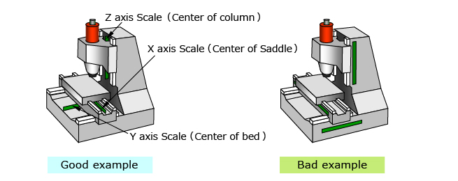
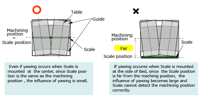
If the yawing occurs on the axis, there is little the influence in the good example, and it is large influence in the bad example.
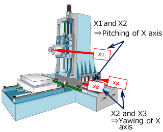
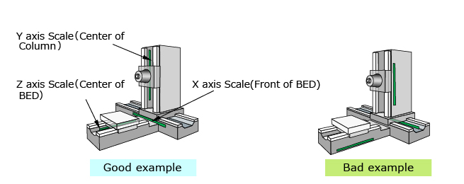
Example of Horizontal Machining Center
As shown in the next figure, when Scale are mounted at the center of the axes at the Y-axis and the Z-axis and Scale is mounted at the front of Bed at the X-axis, the Scale position will become near to the machining position, and so the influence of yawing becomes small.
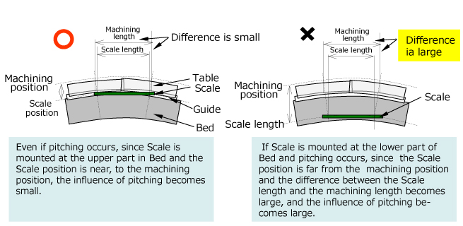
At the Z-axis of the Horizontal Machining Center in the above figure, even if the pitching occurs in the machine in case of good example, since Scale is mounted at the upper part of Bed, and the Scale position is close to the machining position, the influence of pitching is small.
In case of bad example, since Scale is mounted at the lower part of Bed, and the Scale position is far from the machining position, the influence of pitching becomes large.
Example of mounting Linear MP Scale
Example of the X-axis of Vertical Machining Center
The example used the Scale bracket and the Slider bracket is shown.
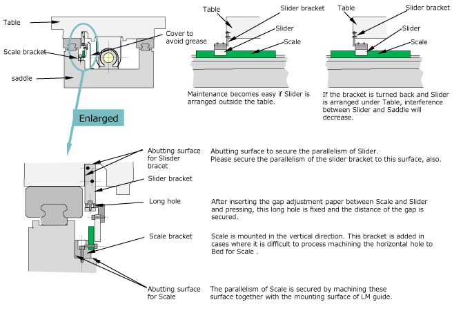
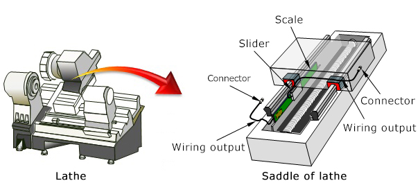
Example of the X-axis of Horizonal Machining Center
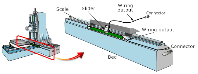
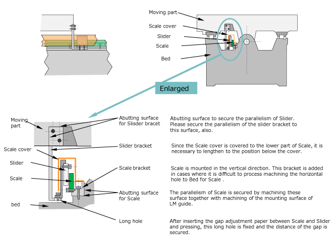
Example of the Z-axis of Horizontal Machining Center(with cover)
The example that Scale is mounted at the nealy center of Bed with the Scale bracket, Slider is mounted with the Slider bracket and Scale and Slider are covered with cover is shown.
The Slider bracket connects to Slider through the lower part of the cover.
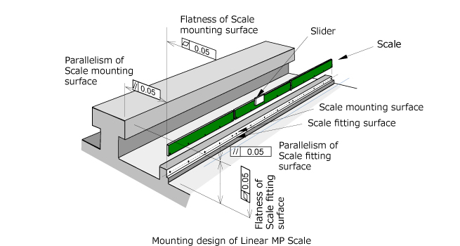
Details of mounting design of Linear MP Scale
The flatness of the plane mounting Scale is 0.05mm and the parallelism is 0.05mm with the guide.
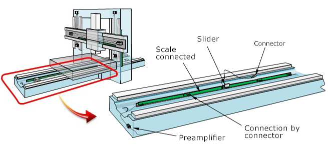
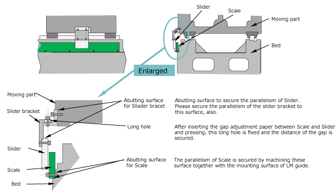
Example of X-axis of the large-sized machine
(In this example, Scale is mounted to Bed and Slider is mounted to Table which is the movable part. )
Example of Z-axis of Horizontal Machining Center
The parallelism and the flatness are specified like the example of the following structure.
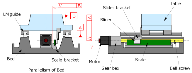
(In this example, Scale is mounted to Bed and Slider is mounted to Table which is the movable part. )
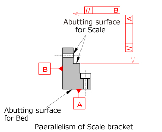
The parallelism and the flatness to the Scale bracket are specified.
Pitch adjustment for Linear MP Scale
When two or more segments of Scale are connected, the pitch accuracy adjustment of mounting segments is required.
- 1.Generally the laser measuring instrument is prepared, the machine movement is measured by laser measuring instrument, and the position of segments is adjusted so that the value detected by MP scale become the same as the value measured by the laser measuring instrument.
If the pitch accuracy of Scale segments is adjusted well, high long accurate Scale can be obtained.
Note) Please equalize the right and left space of the mounting bolt of the central segment, and then install Scale at the beginning
Note) The pitch adjustment of Scale is performed in an order from the central segment.

Accuracy measurement
Accuracy measurement of full stroke Ⅰ
The accuracys of full stroke of forth and back directions are measured with constant pitch.
The accuracys in both Scale feedback and Encoder feedback are measured, and the effect of mounting Scale is confirmed.
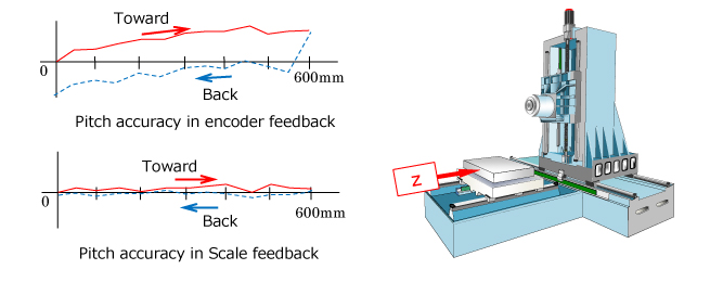
Accuracy measurement of full stroke Ⅱ
Ex)3 measureing points of in X axis of Horizontal Machining Center
1)Compare X3 with X2 and calculate the yawing.2)Compare X1 with X2 and calculate the pitching.