



Lecture 17:The Superconductor Induction Motor
July 2025
NIDEC Technical Adviser
Takashi Kenjo
As discussed throughout this series on the mysteries of electric motors, there is an immense variety of motor types. Selecting the optimal motor for a given application and determining its drive control method are daily challenges and topics of discussion for us. However, this is by no means a simple task. Even if we narrow the scope to electric vehicle (EV) drive motors—a topic studied for over 50 years—current motor science still seems unable to definitively declare a single "best" motor. Electric aircraft are another long-standing dream and a frequently discussed topic today.
So, how does the situation look if we incorporate cutting-edge superconducting technology? I introduced the laboratory of Professor Taketsune Nakamura at the Graduate School of Engineering, Kyoto University, in the January 1, 2024 issue of Transistor Gijutsu SPECIAL [1]. Due to space limitations, the interview portion covering the research background was omitted, so I would like to share it here.
Nakamura: I serve as a Specially Appointed Professor in charge of an endowed chair established at Kyoto University Graduate School of Engineering on April 1, 2017, by Nidec Corporation (renamed to Nidec Corporation on April 1, 2023). Focusing primarily on rotating electrical machines, we explore fundamental electro-mechanical energy conversion processes using various conductive, magnetic, and permanent magnet materials—including superconductors—aiming for optimal design, control techniques, and system integration without being bound by conventional wisdom.
Kenjo: I imagine there are various ways to apply superconductivity to electric motors, but using High-Temperature Superconducting (HTS) materials specifically in the squirrel-cage conductor of a squirrel-cage induction motor is particularly intriguing.
Nakamura: First, superconducting motors cannot operate unless they are cooled to extremely low temperatures. Therefore, it is crucial to minimize the cooling power cost—which acts as a relative penalty—compared to the gains in output and efficiency achieved through superconductivity. Consequently, mainstream R&D generally focuses on HTS materials, which achieve a superconducting state at relatively higher temperatures. To date, applying HTS materials to almost every type of motor has been explored. Modern HTS motors, both in Japan and globally, are predominantly synchronous motors (especially those with HTS field windings). There were very few studies applying HTS materials to squirrel-cage induction motors, but the first solid experimental research came from a group at Sun Moon University (South Korea), whose 2003 paper demonstrated the possibility of synchronous rotation. My supervisor at the time, Professor Kazuya Muta (now Professor Emeritus at Kyoto University), paid close attention to that paper and initiated our investigation.
The Korean group seemingly discontinued their R&D afterward. Meanwhile, in our laboratory, centered around Prof. Muta and supported by talented master's students, we established a basic theoretical foundation. Unfortunately, when Prof. Muta retired and the students graduated and took industry jobs, I deliberated over whether to continue the research. However, having studied the physics of HTS material properties during my student days at Kyushu University, I found it physically fascinating and decided to persevere. At the time, researchers working on HTS induction motors were virtually non-existent worldwide. Furthermore, there was strong skepticism because induction motors intrinsically involve slip, making them inherently lossy. Critics at academic conferences argued that applying low-resistance HTS materials to a squirrel-cage winding would reduce damping effects, making the system unstable and fundamentally impossible to drive.
In response, we methodically addressed each critique through theoretical analysis and experimental validation. Gradually, researchers and engineers at universities, institutes, and companies in Japan and abroad began to evaluate and support our work, allowing HTS induction motors to gain recognition. Today, we have established basic rotational theories, design, and control technologies, and are developing application systems for automobiles and aircraft. We can already prototype 100 kW-class machines at our university, and we plan to develop even higher-output machines in collaboration with corporate partners. Currently, applying this technology to liquid hydrogen pumps is considered the closest superconducting rotating machine application to practical deployment worldwide [2].
Kenjo: In Part 11 of this series, I discussed non-Lorentz forces. A symbolic motor utilizing this force is the hysteresis motor. B. R. Teare derived the torque equation for this motor in his 1937 doctoral dissertation and published an organized theory in AIEE in 1940.
Nakamura: My HTS induction motor also exhibits this characteristic. In a hysteresis motor, the semi-hard magnetic steel itself (coercivity lower than permanent magnets, but higher than soft magnetic materials) controls the magnetic flux state. In contrast, in an HTS induction motor, HTS winding loops surrounding silicon steel sheets control the flux state. Crucially, it achieves high output, high efficiency, and superior acceleration capability—a "smart motor" behavior that conventional hysteresis motors could never achieve. (Note: One of Prof. Nakamura's academic papers on this is listed in Reference [3].)
Kenjo: I have heard that the BCS theory by John Bardeen and others cannot explain high-temperature superconductivity...
Nakamura: The temperature at which a material transitions to a superconducting state is called the critical temperature. According to BCS theory, the upper limit for critical temperature was believed to be around 40 K (-233.15 °C), known as the "BCS wall." However, with the 1986 discovery of cuprate-based high-temperature superconductors featuring critical temperatures far exceeding 40 K—and even 77 K (-196 °C: the boiling point of liquid nitrogen at atmospheric pressure)—BCS theory falls short. Research to establish new theoretical frameworks replacing BCS theory continues today, though a definitive theory remains unconfirmed.
Brief Explanation of Superconductivity via BCS Theory:
A large school of small fish swimming in the sea avoids collisions. Similarly, if electrons in a metal can move through the lattice in large groups without colliding with atomic nuclei, electrical resistance drops to zero. To enable this, a mechanism between electrons is required—explained by the initials of three physicists (Bardeen, Cooper, Schrieffer). In technical terms:
When individual electrons act independently, they follow Fermi-Dirac statistics. However, at extremely low temperatures, pairs of electrons form via the crystal lattice and obey Bose-Einstein statistics, allowing electrons to flow in an orderly manner.
This theory belongs to quantum mechanics (or wave mechanics), which deals with subatomic particles.
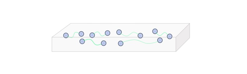
Figure 17-1 Electric current flowing through a conductor represents collective electron motion; collisions with atomic nuclei generate heat, which is the origin of normal state electrical resistance. However, in certain materials below a critical temperature, paired electrons flow smoothly, reducing electrical resistance to zero.
Column: The Intersection of Geniuses — Bardeen and Teare
Many readers likely know John Bardeen as the two-time Nobel Laureate in Physics for BCS theory and the invention of the transistor.
In Part 11, I discussed the wonder of non-Lorentz forces and Benjamin Teare's torque theory for hysteresis motors, showing that expanding his torque formula can also explain inductor motors. Bardeen and Teare were classmates at the University of Wisconsin. In 1928, as they transitioned from undergraduate to graduate studies, Teare switched from physics to electrical engineering, while Bardeen switched from electrical engineering to physics.
Bardeen was driven by curiosity to uncover fundamental phenomena, whereas Teare possessed a keen insight into immediate practical outcomes backed by mathematical rigor. Teare's talents were recognized early, leading to his recruitment by GE.
Later, both worked concurrently at the Naval Ordnance Laboratory in 1941.
Overview of the Superconducting Induction-Synchronous Machine
Let us examine the structure of the motor Professor Nakamura is developing. Figure 17-2(a) shows the conceptual diagram, and (b) depicts the actual superconducting conductor bar used in combination with normal conducting material. For typical squirrel-cage structures, refer to Figure 15-1 in Part 15; for an integrated bar and end-ring squirrel-cage structure, see the photograph in Figure 14-2.
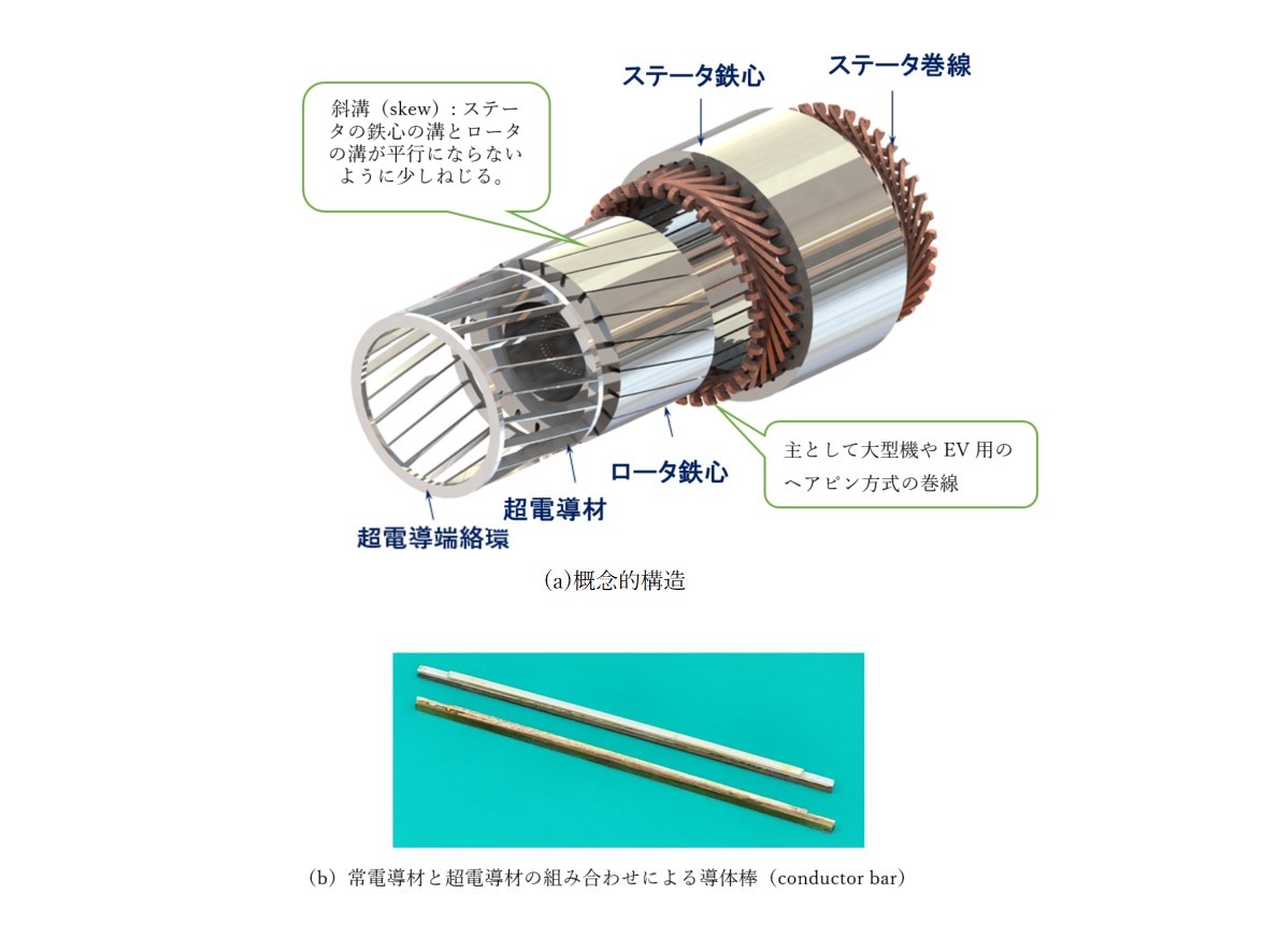
Figure 17-2 Mechanism of using superconducting material in the squirrel-cage conductor of an induction motor rotor.
Figure 17-3 shows a practical implementation of this principle. Figure 17-4 illustrates the assembly of the superconducting conductor. To facilitate basic experimental verification, this motor utilizes a simplified end-ring mechanism. If starting the motor as a normal conductor is required, a separate copper end-ring is also needed for the copper normal-conductor bars.
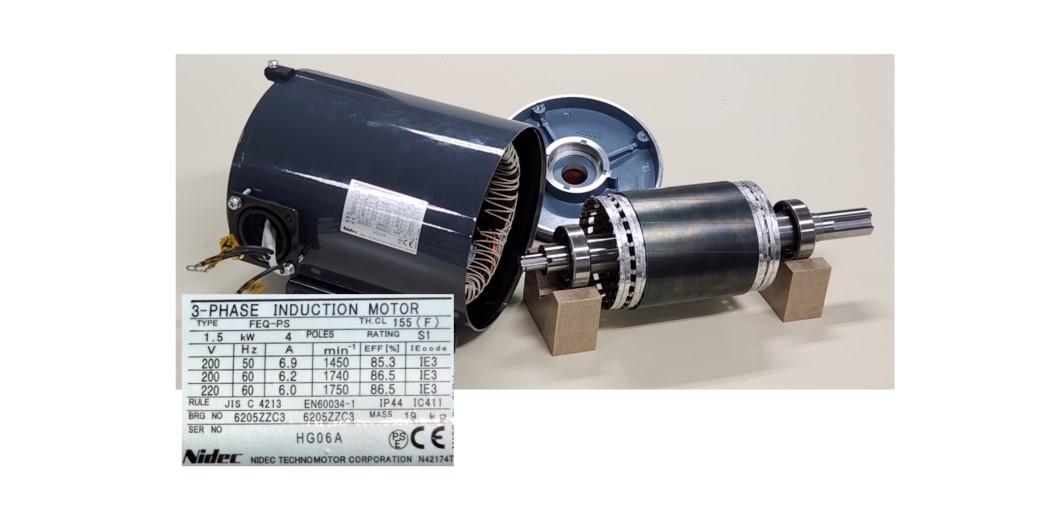
Figure 17-3 An experimental rotor built by modifying a standard 1.5 kW general-purpose induction motor. Disassembled at the Nidec Research and Development Center to inspect its internal structure. The stator features 36 slots with a 4-pole winding. The assembled motor is submerged in liquid nitrogen during testing.
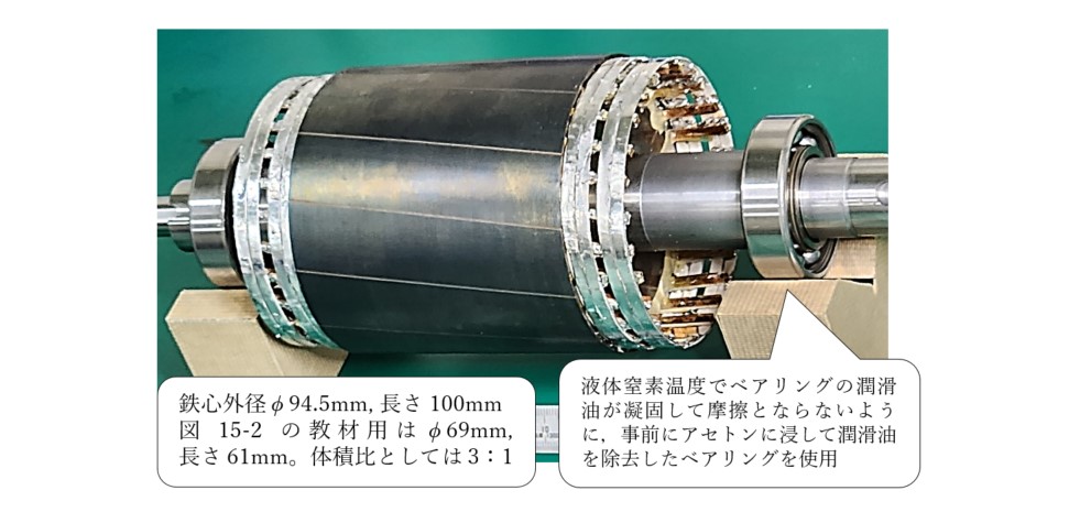
Figure 17-4 Formation of conductor bars and end-rings combining normal and superconducting materials: Tape-shaped superconductors are wrapped around the protruding superconducting bars from the rotor core and soldered into place.
Figure 17-5 shows conceptual cross-sectional diagrams of the rotor structure. (a) illustrates the rotor core cross-section, where the laminated core consists of 0.5 mm silicon steel sheets with conductor bars placed inside 26 closed slots. The core is laser-welded and stacked at 13 locations. (b) shows the conceptual diagram of the end-ring welded assembly.
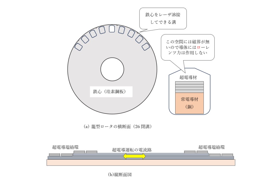
Figure 17-5 Conceptual diagrams of the rotor structure
Induction and Synchronous Characteristics: Synchronous-Asynchronous Availability
The above covered the mechanical structure. Next, let us discuss what performance characteristics emerge from combining this structure with superconductivity.
First, assume DC conditions for the superconducting phenomenon. In the rotor structure shown in Figure 17-4, assume the current flowing through each conductor is constant over time. Even if the current direction and magnitude vary per conductor, as long as the current remains below the critical current at each position, no voltage appears across the conductors. This relationship between voltage and current is shown in Figure 17-6. Below critical current, zero voltage is generated. In this state, the rotor generates a magnetic field fixed relative to the rotor structure, behaving like a permanent magnet motor—meaning it operates with zero slip ( = 0). However, if the load increases under this operating condition, the rotor speed drops slightly below synchronous speed. Induced voltage develops across the rotor windings, producing low-frequency AC current that exceeds the critical current, as shown in Figure 17-7. This state resembles low secondary resistance in a normal induction motor, with the bar current transitioning from DC to a slowly varying AC (~1 Hz).
This allows a smooth transition from synchronous to asynchronous operation—a transition impossible for strong permanent magnet synchronous motors, which suffer from abrupt loss of synchronism ("pull-out") and stall. Weak permanent magnet motors, such as hysteresis synchronous motors, can rotate smoothly even after pulling out of step. This behavior represents the Synchronous-Asynchronous Availability shown in Figure 17-8. The HTS motor automatically acts as an induction or synchronous motor depending on the load, similar to a hysteresis motor, but provides significantly higher pull-out torque.
As noted in Transistor Gijutsu SPECIAL [4], the HTS induction motor starts via slip rotation before locking into synchronous rotation. Slip rotation remains possible even under steady-state conditions, coexisting with synchronous operation. In load tests using a standard 3.7 kW industrial stator core, a maximum synchronous output of 20 kW was achieved. When overloaded further, it delivered more than double its peak synchronous output—reaching 41.3 kW (1,760 rpm, slip = 0.022 at 60 Hz). In short, an output over 10 times the original rating was easily achieved. Under normal operation, it runs at high efficiency as a synchronous motor. When subjected to extreme overload, it autonomously shifts to slip operation, maintaining operation despite losses and demonstrating remarkable overload tolerance.
The prototype in Figure 17-4 was modified from a 1.5 kW motor, and early experiments confirmed an output of 4.5 kW—triple its original rating. Textbooks often explain motor torque using Lorentz forces, but true Lorentz-force motors (like coreless DC motors) are rare. Over 99% of commercial motors rely on non-Lorentz forces, explained by Teare'