



2-1-3 Rotating Speed of DC Motor and Counter-electromotive Force
To further understand torque constant K T , we will think about the case where a motor is running.
The power generating function of the motor is related to this subject.
Power Generating Function and Right-hand Rule
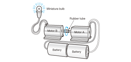
Fig. 2.6 A motor becomes a generator
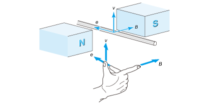
Fig. 2.7 Fleming's right-hand rule
e = BLv ...... (2.5)
e: Generated voltage, counter-electromotive force [V] B: Magnetic flux density [T]
L: Length of wire in the field [m] v: velocity [m/s]
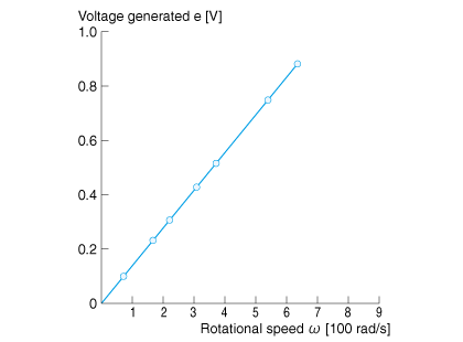
Fig. 2.8 Rotating speed and generated voltage (counter-electromotive force)
Connect the two motors by referring to Fig. 2.6. Connect a miniature lamp to one of the motors and another motor to the power supply and rotate the motor. The miniature lamp will light up.
You will learn from this experiment that a DC motor can generate power.
Now we move the wire across the field at a velocity of v without energizing the motor as Fig. 2.7 shows. We will learn that voltage e is generated in the wire. Let us compare this with the preceding Fig. 2.2.
The direction of the voltage is determined by Fleming's right-hand rule. The direction of the current is the opposite of the direction of the current shown in Fig. 2.2. Since this function reduces the current, it is called a counter-electromotive force. Supposing that the wire is part of the motor winding, we can express wire velocity v as v = ωR by referring to Fig. 2.3. Therefore, the counter-electromotive force that appears in this wire will be expressed according to the following equation:
e = BLRω ...... (2.6)
ω: Rotating speed [rad/s] R: Turning radius [m]
That means counter-electromotive force is proportional to rotating speed ω.
In the case of an actual DC motor, counter-electromotive forces working on all coils are combined and appear between the terminals.
Since it is also proportional to the rotating speed, it is expressed using back-emf constant KE.
e = KEω ...... (2.7)
e: Voltage generated in the motor terminals (counter-electromotive force) [V]
KE: Back-emf constant [Vs/rad]
ω: Rotating speed [rad/s]
When you measure this relationship on an actual motor, it will form a clean straight line as shown in Fig. 2.8.
Actually, back-emf constant KE and torque constant KT are the same thing, which may be verified as follows:
Supposing that the number of coil turns is N, the relationship between generated voltage e and back-emf constant KE will be as follows:
e = 2RNBLω = KEω ...... (2.8)
Here, substituting equation (2.7) for KT = 2RNBL of equation (2.4) and dividing both sides by ω, we obtain
KT = KE ...... (2.9).
If KT and KE are the same for DC motors, what will this mean?
Simply speaking, it means that a motor is a bidirectional energy converter between electricity and machine.
We can interpret that Fleming's left-hand rule views the energy conversion in the direction of "electricity to machine" whose conversion coefficient is KT.
Meanwhile, Fleming's right-hand rule views it in the direction of "machine to electricity" whose conversion coefficient will be KE.
Thus, KT and KE are the same thing. In this book, however, we will continue to use KT and KE separately to clearly indicate the direction of conversion.
Studying Power Generating Function of the Motor
The power generating function also appears while a motor is energized and rotating. To observe such a condition, we will rotate the motor we talked about earlier using step-down alternating current half-wave rectified by a diode for power supply as shown in Fig. 2.9.
Input should have been one half of a sine wave, but we can observe a voltage waveform as shown in Fig. 2.10 between the motor terminals. This refers to the voltage (counter-electromotive force) of equation (2.7) generated by the internal generating function of the motor.
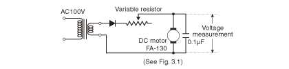
Fig. 2.9 Rotating the motor with a half-wave rectified power supply
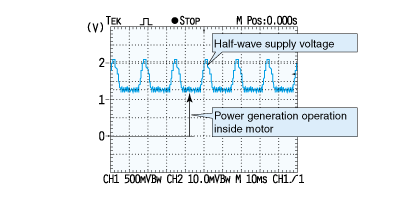
Fig. 2.10 Motor terminal voltage during no-load rotation
Voltage Balance
Fig. 2.11 shows how the power generating function works inside the motor. The figure shows that the sum of voltage drop RaIa caused by winding resistance Ra, voltage drop of the brush contact VB and the internally generated voltage by motor rotation (counter-electromotive force) e = KEω is in balance with external voltage v.
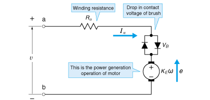
Fig. 2.11 Internal power generation of motor
Here, what will happen if the external voltage rises?
- Voltage difference increases at the ends of winding resistance Ra, causing circuit current Ia to increase.
- As the current increases, torque increases.
- Increased torque increases the motor rotation speed.
- Faster rotation raises counter-electromotive force.
The rotating speed increases in this sequence until the motor reaches a new steady state.
Next, let's see what will happen if the external load is increased while the voltage remains constant.
- As the rotating speed drops, counter-electromotive force will be reduced.
- As a result, a voltage difference occurs on the winding resistor, causing current flow to increase.
- As the current increases, the motor torque increases to balance with the external load.
This time, the motor revolution becomes stable at slower speeds than before.
The DC motor has the following characteristics:
- If the load remains the same, applying higher voltage increases the rotating speed
- If the load increases, the rotating speed drops and the torque increases.
In other words, effects explained by the left-hand and right-hand rules that we thought were different from each other do exist simultaneously in the motor, and the rotating speed of the motor has been determined when the effects are balanced with each other.
Relationship between Rotating Speed and Torque
The relationship between the rotating speed and torque of a DC motor can be shown by the diagram shown in Fig. 2.12.
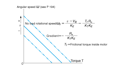
Fig. 2.12 Rotating speed and torque of DC motor
When the supply voltage is constant, the diagram shows that DC motor characteristics can be represented by a straight line going in the direction from top left to bottom right.
You can read the no-load angular speed at the upper left-hand end of the line and the starting torque at the lower right-hand end. In addition, if the supply voltage rises, this line moves in parallel toward the upper right-hand corner; and, conversely, toward the lower left-hand corner if the voltage drops.
You already learned that a DC motor has a feature of increasing torque in proportion to current. This time, we have learnt that it has another feature in which rotating speed increases if voltage is increased. This is quite a convenient characteristic in terms of controlling rotation.
Another noteworthy characteristic is that the DC motor generates torque proportional to the current even if the rotating speed is zero because of the T = KT relationship (equation 2.3). This means that the stop position can be maintained by controlling the current even if a large external force is applied during position control.
This is a characteristic of DC motors and brushless DC motors only and is not found on induction or stepping motor. DC motors and brushless DC motors are used for servo control due to this feature of being able to maintain the stop position.
<Short column> N-T characteristics
Supposing the unit of rotating speed is [rpm], the relationship with torque is occasionally called N-T characteristics.
Actual Example of Coreless Motor
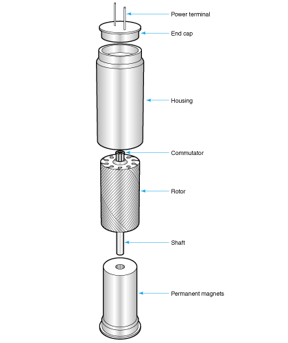
Fig. 2.13 Structure of coreless motors
Among the motors we have thus far studied, the practical motors that are most similar to motors that have no cores are the so-called coreless motors, or moving coil motors.
As its name suggests, the coreless motor does not use a core for the rotor. Instead, it uses a coil hardened with resin for the rotor. Fig. 2.13 shows an example, and Fig. 2.14 shows a sectional diagram.
Another type of coreless motor has a flat coil. Because this motor is manufactured using the same method as that for printed-circuit boards, it is called a printed motor.
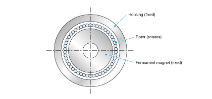
Fig. 2.14 Sectional view of coreless motor
Not using a steel core for the rotor produces a number of advantages, as follows:
- Small moment of inertia enables prompt actions. (*Note)
- Rotor that is not affected by magnetic attraction ensures smooth rotation.
- Low inductance plays a significant role in preventing sparks from occurring during rectification.
- Low likelihood of spark generation reduces brush wear.
- Less wear enables metallic brushes to be used, reducing the drop in contact voltage while increasing motor efficiency.
However, it is not without disadvantages.
- To downsize or develop a high-performance coreless motor, alnico, rare earths and other expensive magnets are required.
- High coil manufacturing costs.
- Production cost increases if precious metals are used for brushes and commutators.
As a result of the above, coreless motors did not enter mainstream use for mass supply at inexpensive prices. They have been used in compact equipment, measuring instruments, and precision control motors.
However, in recent years, through utilization of their compact size, they have been used in mobile phones as a vibration motor (pager motor). Now, they have become one of the motors we use most commonly.
Although not a coreless motor, there is a motor with the coil wound around the cylindrical core. Unlike ordinary DC motors, the core of this motor is not slotted; thus it is called a slotless motor.
The core of a slotless motor rotates together with the coil, and it operates according to a principle almost identical to that of coreless motors. The slotless motor had been used as a high-performance control motor until the brushless DC motor debuted.
*Note: Printed motor has a flat-shaped coil; thus, its moment of inertia is not small.