


2-1-5 Rotation Principle of DC Motor with a Core Slot
To return to the first question, by its very nature, iron is approximately 1,000 times more magnetically conductive than air. Due to this nature, magnetic field lines are concentrated in the core of the slotted rotor as Fig. 2.18 shows, while the magnetic fields of the coils become extremely weak. Such a condition prevents the BLI law that states "to the wire placed in the magnetic field..." and the premise of counter-electromotive force that says "the wire transverses the magnetic field..." from holding.
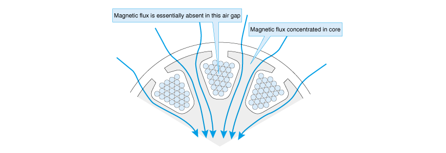
Fig. 2.18 Magnetic flux concentrating on the core
If you turn the motor shaft with your fingers when the coil is not energized, you may feel some rugged anti-drag resistance caused by the rotor teeth and permanent magnets. This phenomenon is called cogging.
You cannot check the influence of cogging by quoting the BLI law or looking at the premise of counter-electromotive force for an explanation.
So, we will try to explain the principle of torque generation of a cored motor from two aspects.
(A) Explanation Based on the Tension of Magnetic Field Lines
The BLI law cannot explain mutual attraction or repulsion of magnets, or the force with which a magnet attracts nails. That is, force generated by magnetism is difficult to explain as an effect of the current in a magnetic field. In fact, they are related in the field of physics.
There is a method of integrally explaining the above based on the concept of magnetic field lines. Magnetic field lines tend to contract like a rubber cord. If magnetic field lines are bent by energizing the wire placed near iron, force works on the lines to make them straight. Fig. 2.19 explains DC motor torque generation according to this principle.
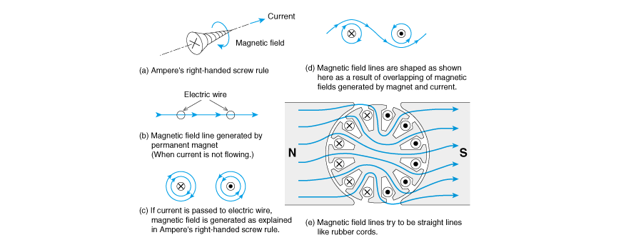
Fig. 2.19 Explanation using the right-handed screw rule concerning electric currents and magnetic fields
<Short column> Dot and Cross (Dot and cross)
The Dot in Fig. 2.19 is referred to as a dot and indicates a direction of movement from the back to above the surface of the paper.
Conversely, the Cross is referred to as a cross and indicates a direction of movement from the reader to the paper surface. If you compare this figure with the diagram of screw in Fig. 2.19 (a), you may be able to easily remember the above.
(B) Explanation and Calculation Based on Counter-electromotive Force
In the item on the power generating function of a motor, I explained that the torque constant and back-emf constant are basically the same thing. Here, if we review Fig. 2.8, we will understand that the counter-electromotive force is also generated from a slotted core motor for models.
Rather than thinking that the wire is cutting across the magnetic field, we can think that counter-electromotive force is generated as a fraction of chronological changes in the magnetic flux that interlinks the coil as Fig. 2.20 shows, and then it is rectified by the brushes and commutator (AC/DC conversion) and observed as the counter-electromotive force of the direct current.
Fig. 2.20 Changes in interlinkage magnetic flux and counter-electromotive force
As we studied in equation (2.9), KE and KT are the same thing. Therefore, we will observe the counter-electromotive force instead of analyzing torque, and we let the obtained KE be KT as is, then torque calculation becomes possible. This is the second method of explanation.
Now, how should we consider cogging when applying this method? Simply speaking, you just add this element to the calculation.
There are several methods for calculating cogging torque, but they all require complex mathematical expressions that are difficult to understand.
This book will not go into detailed description of the above method but only mention it for your information that it can also figure out the torque of a cored motor. For more details, please refer to reference material [1].
[Literature]
[1] Kenjo and Nagamori; New Brushless Motor, Chapter 5, Sogo Denshi Shuppansha
The theory developed in said book is part of the basics, however, we believe this is the only book that has yet been published that describes basic principles yet unknown to specialists in this field. This book may be a little difficult for novices to tackle, but those aspiring to be motor specialists will hopefully attempt to read it.
<Short column> Interlinkage
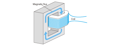
Magnetic flux and coil are linked like chains as shown in the following figure.
This is what the term "interlinkage" means. This term is used in association with the number of coil turns of motors and transformers. Interlinkage magnetic flux refers to the product of flux (unit: Wb, weber) and the number of coil turns.