Application-oriented research on internal generating polishing
M.Sc., P.E., Noritaka Fujimura, Nidec Machine Tool Corporation, Ritto, Japan
M.Sc. Patrícia de Oliveira Löhrer, WZL of RWTH Aachen University
Abstract
The application of polishing process in gears has two main purposes. (1) Improvement of durability by decreasing the risk of micro cracks growing on surfaces. (2) Possibility of transmission efficiency increase and better NVH (Noise Vibration and Harshness) performance. Durability improvement is the main motivation for truck, bus and agriculture applications. Efficiency and NVH requirements are increasing, especially for electrified vehicles. For external cylindrical gears, grinding, honing or polishing are established processes for hard finishing after heat treatment. But for internal ring gears, hard finishing using grinding, honing or skiving are still limited, and the technology readiness of internal gear polishing is on the development level.
This paper describes the influence of the polishing process on the surface quality of internal ring gears using the process of internal generating grinding. For the initial investigation, different process parameters with polishing wheels were tested. In the end, mirror-like flank surfaces with Ra = 0.05µm and Rz = 0.39µm were achieved, and the process parameter influence on the surface features were obtained. Finally, the most productive process parameters for the target surface features are proposed.
1. Introduction and Motivation
On the trend of integrated power train development, planetary gear stages can provide a higher transmission ratio in a significantly more compact and lighter package than conventional power trains, leading to a positive effect on the efficiency of the overall system [1]. At the same time, the application of planetary gear sets encounters new challenges, especially concerning noise and vibration behavior [2]. For this type of gears, even the slightest geometric distortions in the ring gear will lead to unwanted noise and vibration. These unwanted excitations are easily perceptible in electrified vehicle transmissions, which rely on fewer elements in comparison to conventional combustion engine transmissions [3]. Due to this, the requirements for the ring gear quality have increased in the last years and the importance of hard finishing for these gears has increased as well.
Gear quality is categorized into geometry and surface features. Geometry deviation can be a cause of excitation force that leads to noise. A smooth surface feature which decreases the risk of micro cracks growing is expected to improve endurance of the gear, as well as the noise behavior and the efficiency. Increase of endurance is the main motivation for truck, bus and agriculture applications. Noise, Vibration and Harshness (NVH) and efficiency improvement is more relevant for high rotation speed powertrain/transmissions such as in electrified vehicles.
For hard finishing of external gears, generating gear grinding and polishing are used frequently in mass production, due to their high productivity combined with high quality. These processes have been intensely investigated in the last years, in different research [4, 5, 6]. Grinding is applied to achieve the required geometries and polishing is applied to reach lower surface roughness in a range below Ra0.1µm, and Rz1.0µm.
For internal ring gears, hard finishing applications using grinding, honing or skiving are still limited. Internal generating gear grinding is a hard finishing process developed and patented by NIDEC MACHINE TOOL CORPORATION, aiming at the manufacturing of internal gears with high quality while considering the productivity requirements of mass production. This high productivity is achieved by a unique grinding wheel design matched to a high precision spindle and a cross-axis angle. Since 2009, this process has been used for serial production and effect of geometry improvement was evaluated [7]. More detailed research for the productivity and the economic evaluation of internal generating grinding with corundum and cubic Boron Nitride (cBN) grain wheel was investigated by Fujimura et al. [8, 9]. However the surface roughness was up to Ra0.35µm. To obtain benefit by a smooth surface feature with less than Ra0.1µm, polishing process for internal gears by utilizing the same kinematics of the internal generating gear grinding with resinoid wheels was investigated in this work.
2. State of the Art
Internal generating gear grinding is a hard finishing process with geometrically undefined cutting edges. Similarly to external generating gear grinding, the tool used in internal generating gear grinding has threads that engage continuously from one tooth after another in the gear. Simultaneously, the grinding wheel moves in axial direction to complete the grinding process along the whole flank [10]. The sliding speed between the flank of the gear and the grinding wheel can be typically up to 30m/sec. To enable this process, two distinguishing features on the machine are very important: the grinding wheel shape and the tool spindle, see Fig. 1.
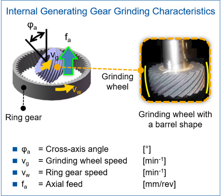
The relative sliding motion between a gear and a grinding wheel is obtained by a cross-axis angle φa, as shown in Fig. 1. The cross-axis angle would normally cause an interference between a tool and a gear, if the tool would have a strict cylindrical shape. Therefore, a barrel shaped design for the grinding wheel is used, as shown in the right of Fig.1. The grinding wheels curvature avoids the interference and optimizes the contact pattern with the gear flanks.
The second feature to enable the process is a high-speed precision spindle. At up to 15,000min-1, the tool can be meshed with the existing teeth of the gear precisely and provide high sliding speed. A special internal cooling system minimizes spindle heat distortion and allows the process to meet the high requirements of the finished internal gear in a mass production scenario.
In previous research by Fujimura et al., the productivity of the internal generating gear grinding process was investigated considering the influence of process parameters, such as cutting speed and radial infeed [7]. In the research, the most suitable setup of process parameters was found, considering not only the process productivity but also the gear quality in terms of geometry and roughness [7]. Fig. 2 shows the quality results obtained in the work of Fujimura et al. [7].
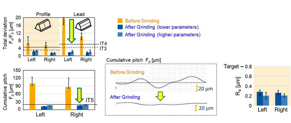
It is possible to see that the deviation in profile and lead direction was below the class IT3 of the ISO system for cylindrical gears tolerance classification [11] for all the process parameters setups investigated. The study further showed positive correction of pitch line runout Fr and cumulative pitch error Fp, removing the distortions from the heat treatment, as shown lower of Fig. 2. Surface roughness better than Ra0.35µm was obtained constantly as shown in Fig. 2. These results were obtained as a grinding process with corundum or cBN grain wheels to improve geometry and surface.
However the surface roughness by grinding, Ra0.35µm, is not enough to obtain benefit by smooth surface described in Chapter 1. Farther process development with resinoid wheels to achieve the surface roughness less than Ra0.1µm is desired.
3. Objective
Based on the research gap highlighted in the chapter before, the objective of this work is to investigate the influence of the process parameters on the resulting gear quality and flank roughness for polishing. In the next chapter, the test design used to achieve the objective of the research will be introduced. In chapter 5, the influence of process parameters investigated on the resulting gear quality and flank roughness will be presented. Chapter 6 and 7 show the conclusion of this paper by reiterating the core results and highlighting the most productive process parameters for this application as well as possible improvement areas.
4. Materials and Methods
In this chapter, wheel specifications, part specifications, process parameter sets, target values and inspection methods are described. At first wheel specifications.
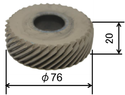
Specifications of polishing wheels available in the market are limited. In order to select a proper polishing wheel for the trials of this research, a pre-trial was performed. In this pre-trial, polishing wheel with different grain sizes and type of binding were investigated, according to their ability to perform the polishing process with high quality. Based on the results of this pre-trial, a wheel with resin bonded corundum of grit size 800 mesh was chosen. The wheel dimensions are diameter 76mm x width 20mm as shown in Fig. 3. The same specification was used for all trials.
For all the grinding trials, the same ring gear specification was used. Table 1 describes the main specification parameters of the ring gear. The geometry of the ring gear and its dimensions were selected based on automotive applications.
| Name | Value | Unit |
|---|---|---|
| Module mn | 1.25 | mm |
| Number of teeth z | 85 | |
| Helix angle β | 20 | deg. |
| Profile angle α | 20 | Deg. |
| Tip diameter da | 111.17 | mm |
| Root diameter df | 116.92 | mm |
| Addendum modification factor |
0.3 | - |
| Gear width b | 30 | mm |
| Hardness | HRC 60 | |
| Material | SCR415 JIS (Equivalent to16MnCr5 DIN) |
To investigate the influence of polishing process parameters, a design of experiment with 9 test points was defined as shown in Fig. 4. The wheel speed, the radial infeed and the axial feed were chosen as variable. The wheel speed can be converted into the sliding speed with cross axis angle φa in Fig.1. The wheel speed is indicator to the machine performance related to heat distortion, synchronization. The sliding speed is related to the process performance between a wheel and a part surface. A wheel speed of 1,500 to 11,945 min-1 represented sliding speed of 3 to 24m/s with 30dgrees cross axis angle. The axial feed was set from 0.02 to 0.04mm/part-revolution. These wheel speed and axial feed were directly influencing the process time, thus the productivity. Radial infeed was varied from 0.02 to 0.25mm.
For trials, parts which were already ground were used. For each test point, the tool is dressed before the execution of the test. The polishing process was executed in one pass.

The polished parts were evaluated in terms of geometry, surface roughness and grinding burn. The geometry of the parts was measured in a gear measurement center P65 from the company Klingelnberg. The total deviation in profile and lead direction are measured. A limit of IT5 was defined for the classification of a good quality in the part. The surface roughness was measured by a tactile measurement device. The measurement was performed in profile direction, in the middle of the tooth flank. A total measurement length ln of 1.5 mm was used. The measurement length was evaluated with a cut-off wavelength λc of 0.25 µm. The parameters of Ra and Rz were evaluated. A limit of Ra 0.1 µm and Rz 1.0 µm was defined for the classification of a good quality in the part. Finally, the grinding burn was evaluated with the nital etching technique.
5. Test Results
5.1 Influence of radial infeed
In this chapter, the influence of radial infeed is shown and discussed. As mentioned in the previously chapter, the radial infeed was varied in 5 levels, at test point No. 1 to 5 in Fig. 4. Its influence on the roughness parameters is shown in Fig.5. The left graph shows by Ra, the right shows by Rz. The surface roughness was decreasing with increasing radial infeed, but no further decrease was observed for a radial infeed greater than 0.15mm. At a radial infeed of 0.10mm or greater, the target Ra0.1µm was achieved. Due to similar trend between the Ra and Rz values, only results of Ra are shown on this paper here after.
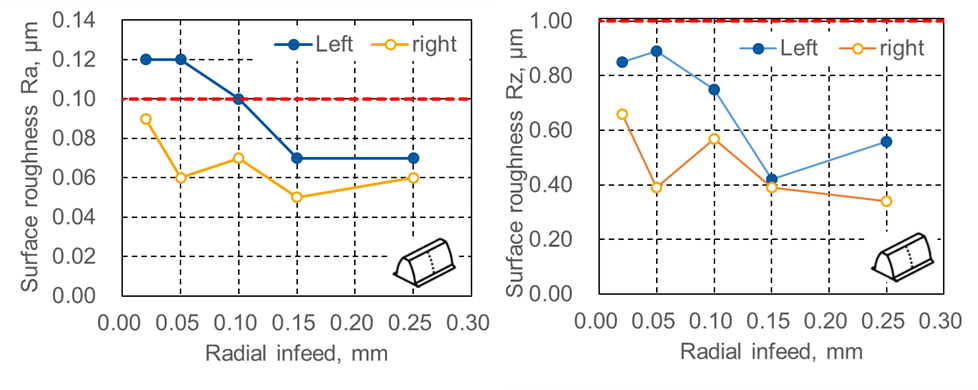
Fig. 6 shows geometries after polishing by Fα total profile deviation, Fβ total lead deviation. With radial infeed smaller than 0.15mm, Fα and Fβ were stable well within IT5. But at radial infeed 0.25mm, Fα and Fβ were increased up to IT5 criteria. Fig. 7 shows gear protocols before and after polishing at radial infeed 0.1mm. No significant change of gear protocols was observed. B.B.D. (Between Ball Diameter) was increased 0.004mm which is within variations of grinding process. From these results, it is indicated that radial infeed 0.15mm is the limitation to keep geometry by polishing.
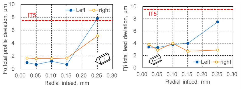
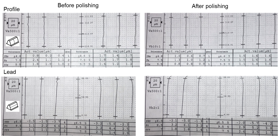
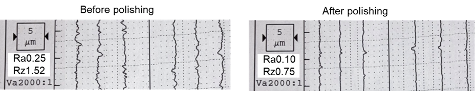
Fig. 8 shows the surface feature before and after polishing at radial infeed 0.1mm. Peaks of roughness curve were removed by polishing.
5.2 Influence of spindle speed
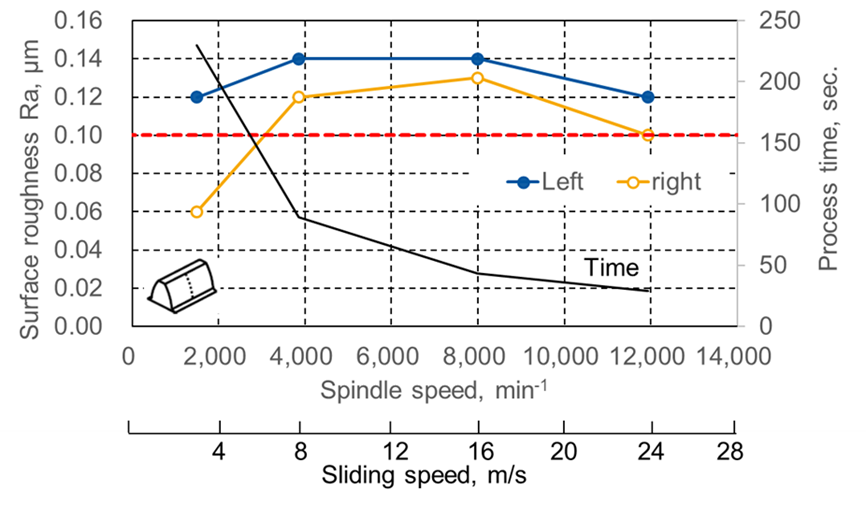
In this chapter, the influence of spindle speed is shown and discussed. As mentioned in the previously chapter, the spindle speed was varied in 4 levels, at test point No. 2, 6, 7, 8 in Fig. 4. Its influence on the roughness parameters is shown in Fig.9. On both flanks, high non-linear influence was absorbed. Slow sliding speed of 3m/s at 1,500min-1 of the spindle provided the smallest roughness, after that roughness increased with higher spindle speed, and at 24m/s, 11,945min-1, roughness was decreased again. The black line in Fig. 9 shows the process time. At 1,500min-1 the process time was 230sec., and it can be reduced to 29sec. at 11,945min-1. From these results, it can be expected that at 11,945min-1 small surface roughness as similar as at 1,500min-1 is obtained with 7.9 times higher productivity.
5.3 Influence of axial feed
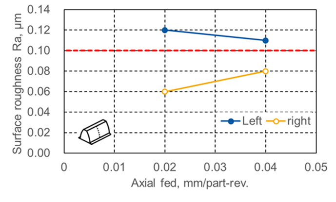
In this chapter, the influence of axial feed is shown and discussed. As mentioned in the previously chapter, the axial feed was varied in 2 levels, at test point No. 2, 9 in Fig. 4. Its influence on the roughness parameters is shown in Fig.10. By increasing the axial feed from 0.02 to 0.04mm/part-revolution, the surface roughness Ra on left flank decreased by 8% from Ra0.12 to 0.11, and on right flank increased 33% from Ra0.06 to 0.08. This indicates that independent pass separated on left/right flank with different axial feed has possibility to obtain the required surface roughness.
5.4 Grinding burn
No grinding burn was observed on all test points. Fig. 11 shows examples of nital etching inspection results.
6. Conclusion
The first polishing trials of continuous generating process for internal gears were conducted, and the following facts were found.
The influence of three polishing process parameters, such as the wheel speed, the radial infeed, and the axial infeed were investigated. Radial infeed amount was directly connected to surface roughness. The surface roughness was improved by increase of radial infeed. Larger radial infeed than 0.1mm obtained surface roughness less than Ra0.1µm and the radial infeed 0.15mm achieved Ra 0.05µm. The radial infeed 0.15mm is the limitation to keep geometry.
As the wheel speed increased from 1,500min-1, the roughness increased, but once it exceeded 8,000 min-1, it tended to decrease again to the same level as 1,500min-1. The wheel speed is the main factor that determines productivity. At 11,945min-1, the process time can be reduced to 1/8 of one at 1,500 min-1.
The axial feed had different influence on the right and the left flank. The roughness Ra increased by 33% on the right, but decreased by 8% on the left by an axial feed change from 0.02 to 0.04mm.
No grinding burn was detected at all test points.
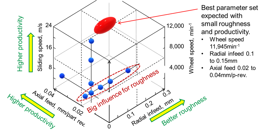
From these results above, the parameter set of the radial infeed 0.1 to 0.15mm, the wheel speed 11,945min-1, the axial feed 0.02 to 0.04mm/p-rev. have possibility to provide surface roughness better than Ra0.1 with the highest productivity. See Fig. 12. Different axial feed on left and right flank could be a solution to obtain small surface roughness, too.
7. Outlook
For the next step, polishing trials with the best process parameters defined by this research are planned to confirm. Additionally, repeatability evaluation by several polishing trials at the same process parameters will also be executed. Though this research, one specification of polishing wheel was chosen. Wider possibilities can be expected by trials with different wheel specifications. To investigate the effect for industrial applications, detail surface roughness investigations by Rpk, Rvk are valuable.
8. Reference
- 1.Klocke, F.; Brecher, C.: Zahnrad- und Getriebetechnik. Auslegung – Herstellung – Untersuchung – Simulation. Munich: Hanser 2017
- 2.Pinnekamp, B.; Heider, M.; Beinstingel, A.: Dynamic behavior of planetary gears. Power transmission engineering, June 2020, p.42-47.
- 3.Ahmad, M.; Brecher, C.; Löpenhaus, C.: Einflussanalyse von langwelligen Abweichungen auf das Anregungsverhalten von Getrieben für Elektrofahrzeuge. Schweizer Maschinenelemente Kolloquium, 2018.
- 4.Ophey, M.; Reimann, J.: Prediction of surface zone changes in generating gear grinding. AGMA Technical Paper, 2014.
- 5.Reimann, J.: Randzonenbeeinflussung beim kontinuierlichen Wälzschleifen von Stirnradverzahnungen. Doctorate Thesis, RWTH Aachen, 2014.
- 6.Lang, Martin.; Load carrying capacity of superfinished tooth flank surfaces depending on function-oriented roughness parameters, RWTH Aachen, 2022
- 7.Fujimura, N.; Hard Finishing – Internal generating gear grinding as a hard finishing process enables significant noise, vibration and harshness improvements in EV transmissions, technical magazine, Transmission Technology International, Dorking 2021, p.63-64
- 8.Fujimura, N.: Practical analysis on productivity of grinding tools in the process of internal generating gear grinding, 4th International Conference on Gear Production 2021
- 9.Fujimura, N.: Practical analysis of productivity of grinding tools in the process of internal generating gear grinding, 16th CIRP Conference on Intelligent Computation in Manufacturing Engineering, CIRP ICME ‘22,
- 10.Yanase, Y.; Ochi, M.; Nakamichi, Y.; Nishimura, U.; Ashizawa, Y.: The World's First Machine for Grinding Internal Gears in Planetary Gear Systems. MHI Technical Review Vol. 46 No. 3: 2009
- 11.DIN ISO 1328-1 - 2018-03 Cylindrical gears - ISO system of flank tolerance classification, Beuth Verlag 2018