Glossary of Motor Terms
Reluctance motor
A reluctance motor is a type of synchronous motor, also known as a synchronous reluctance or reluctance synchronous motor. Reluctance motors are divided in two types; one is powered by single-phase or poly-phase mains with 50/60Hz, and the other is powered via a three-phase inverter using a position sensor. Either type uses a stator in a distributed winding configuration.
Mains’ driven type
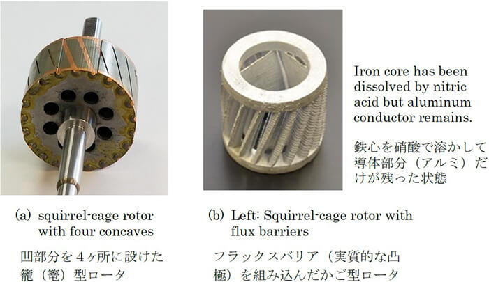
The rotor of this type is a combination of squirrel cage and flux barriers. Two typical types are shown in fig. (a) and (b). The flux barrier is a design intended to form low-reluctance flux paths and high-reluctance flux paths. In (a) the convex (or salient) poles provide a low-reluctance airgap (q-axis), while the concave potions provide high-reluctance gaps (d-axis). When power is supplied, the motor starts up, accelerates as an induction motor, and eventually is brought into synchronism with the power supply frequency. The synchronous speed differs between 50 Hz and 60 Hz areas.
Inverter-driven type
Figure (c) shows a typical rotor structure with no conductors embedded in the flux barrier holes or grooves. To start and accelerate this motor,the rotor angle must be detected to generate proper switching signals to drive the inverter. The speed can be set automatically or controlled in this scheme.
Term List (R)
- Rare earth magnet
- Reactive power
- Rectification via commutator
- Regenerative brake
- Reluctance motor
- Remanence,Remanent magnetization
- Resolver
- Reversible motor
- Revolutions per minute (rpm)
- Revolutions per second (rps)
- Revolving field (Rotating field)
- Revolving field motor
- Right-hand screw law
- Ring spring
- Riser
- RMS (Root-mean square) value
- Rotor, Stator
- Rotor cross-sectional structures