Quest For Motors' Hidden Abilities and New Potentials
Lecture 8: The Advances in Semiconductor Technology that Created the Field of Power Electronics
Brushless technology which was initially adopted in small motors spread to mid-sized and large motors. This was made possible by advances in semiconductor technology that took place in Japan the United States, and European countries. The electronic technology to drive and control motors has come to be referred to as power electronics.
1. Analog and digital
There is a general perception that electronic technology was first developed for analog devices then later greatly expanded with digital applications. In the use of semiconductor devices for motor control, however, advances occurred side by side in analog and digital devices. The stepping motor is a typical example of the latter. This motor is used for positioning control (i.e., moving an object from one position to another in a precise manner). The servo motor is used for the same purpose but is analog-controlled; it was developed by modifying the DC motor for this application.
What do we mean by analog? This is explained in Fig. 1. We shall consider the control of a DC motor. There are two terminals, A and B, and we assume that an electronic circuit is used to control the voltage on terminal B. Since the supply voltage is V, the motor is subjected to a voltage which is obtained by subtracting the voltage at terminal B motor from V. In analog control, the voltage applied to the motor is controlled in a continuous, smooth manner, which has the advantage of achieving a smooth rotation, but the transistors or other semiconductor devices are subjected to the difference between the supply and motor voltages. The product of this voltage difference and the current flowing is the power consumed in the electronic device. For example, if there is a 5V voltage difference and 4A current flow, a loss of 20W occurs. This generates heat and raises the temperature, which can lead to impairment of the semiconductor's function.
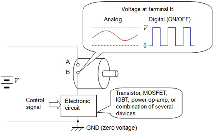
The other method is the digital one. Here, control is done to achieve either of two states, application of the supply voltage, V, or 0, and their respective times. The stepping motor is controlled by a relatively simple digital method. A method widely used today is Pulse-width modulation, which is used to control brushed and brushless DC motors. This is explained in some detail in Fig. 2.
2. Birth of the field effect transistor and its hybrid with the junction transistor
In the previous volume, I wrote that the appearance of the junction transistor and further improvement of its performance were instrumental in advancing brushless DC motors. However, the junction transistor had a shortcoming as a switching device. This was the need to pass current between the base and emitter to switch it on, which makes for a less-than-ideal switch. Although it may seem that there is no problem since a low current is used to control the ON/OFF of a large current, the consumption of power in the control circuit raises the temperature, so that there is a limit to how small the circuit can be made.
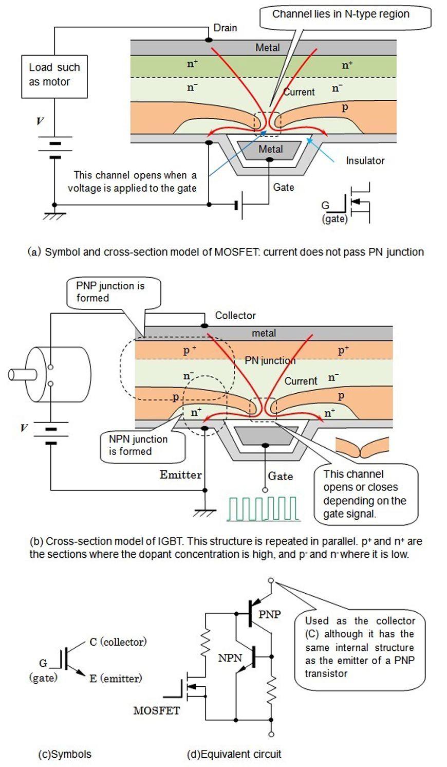
The field-effect transistor, which was subsequently developed, employs a semiconductor microstructure which makes it possible to switch the current ON/OFF using a low voltage and with very little current. The metal-oxide-semiconductor field-effect transistor (MOSFET) commonly used today is a field effect transistor. The current path is provided by the N- or P-type semiconductor. The former, which employs electrons as current carriers, is usually used since it allows the passage of large currents through a small area. Figure 3(a) shows a typical cross-section structure. With this method, based on semiconductor microfabrication and parallel coupling, it became possible to control very large currents.
MOSFETs have the following three features.
(1) A simple circuit is used to process the switching signals.
(2) The voltage drop in the ON state is extremely low. In other words, the power loss is low.
(3) The higher the frequency of PWM, which is described below, the more suitable for producing a smooth current.
The insulated-gate bipolar transistor (IGBT) combines the advantages of the MOSFET (voltage control) and bipolar transistor (current passage through the PN junction allows the control of large power). A typical structure is shown in Fig. 3(b). The entrance of the control terminal consists of a MOSFET and the interior which controls current consists of a bipolar transistor.
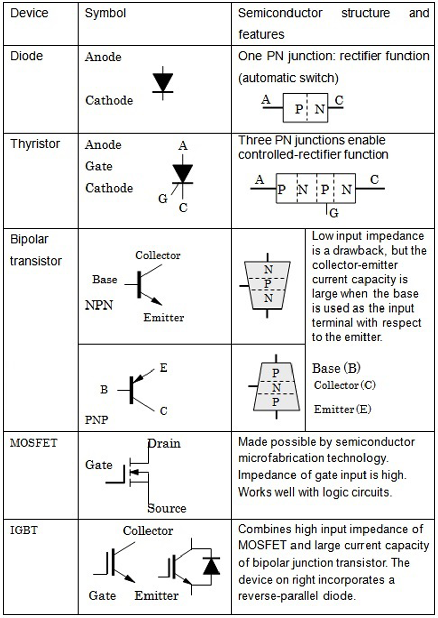
Table 1 summarizes the symbols and functions of the various semiconductor devices that were developed.
3. Pulse-width modulation
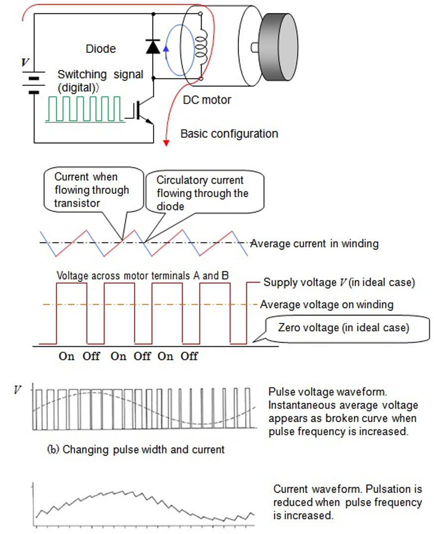
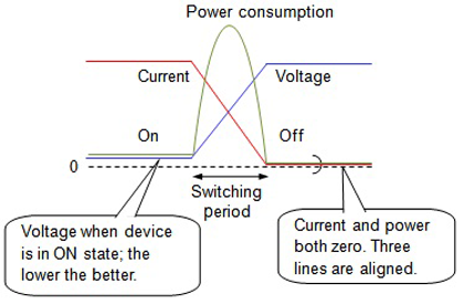
Pulse-width modulation (PWM) is the main method of driving motors using semiconductors today. PWM, which employs digital signals (ON/OFF), can reduce losses within the transistor. The principle involved is illustrated in Fig. 4. There are three elements, each of which plays a significant role.
(1) There is no power loss in the IGBT if the switch is fully on and the drain-source voltage is zero. The motor winding is subjected to the supply voltage.
(2) There is no power loss if switched off completely, i.e., the current is zero. At this time, the winding current passes the diode and circulates. Although a slight voltage (0.6V) appears on the terminals of diodes, it is assumed to be zero in an ideal treatment.
(3) Current pulsation is low when ON/OFF switching takes place rapidly. However, losses occur in the device (transistor or IGBT) during the transition period from on to off. It was for this reason that considerable efforts were spent on developing a device with low loss at fast switching frequencies.
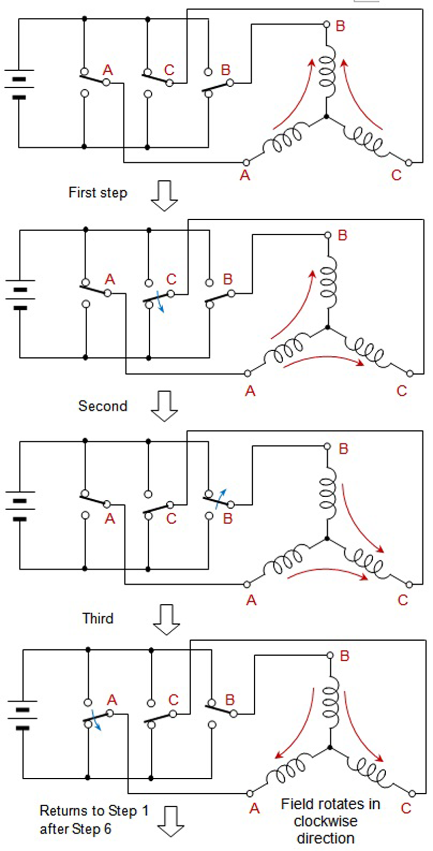
4. Inverter and its uses
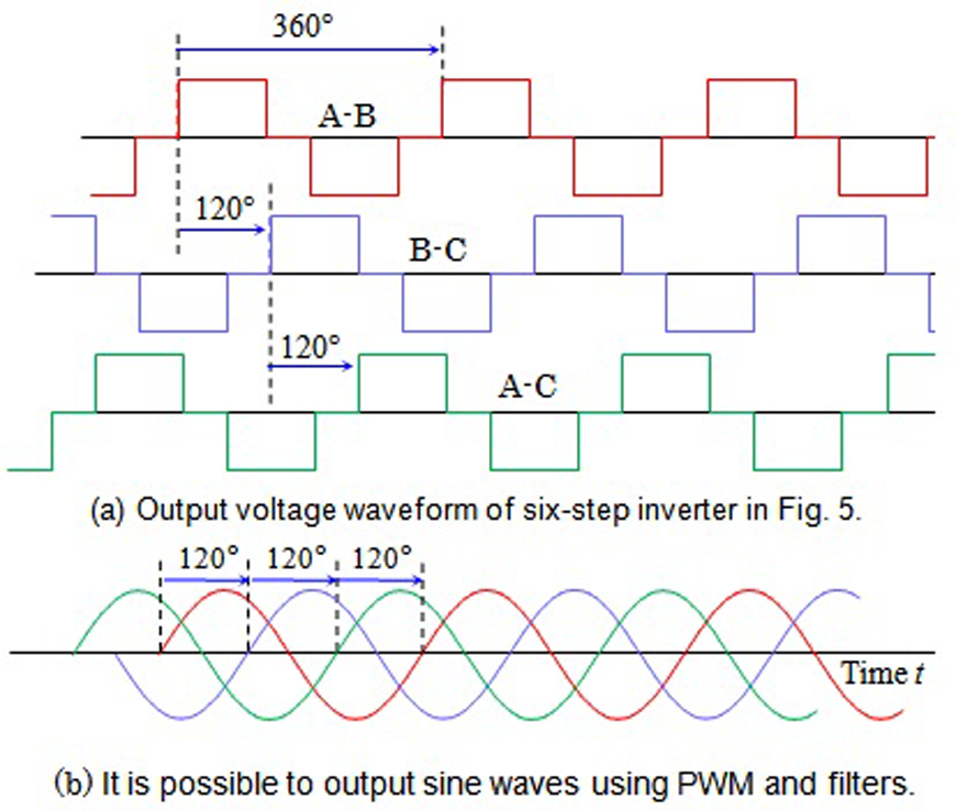
An electronic circuit that converts direct current into alternating current is called an inverter. A device that converts alternating current into direct current is called a converter, so the name "inverter" means that it converts in the inverse direction. Today, the term inverter usually refers to a device that converts direct current into three-phase alternating current, consisting of three switches. The principle is shown in Fig. 5, which indicates that three switches are needed. By flipping the switches up or down in proper sequence, the voltages between the A, B, and C terminals display a square-wave alternating voltage, as shown in Fig. 6(a). A 120-degree phase difference exists between A-B and B-C, and a 120-degree phase difference between A-B and A-C.
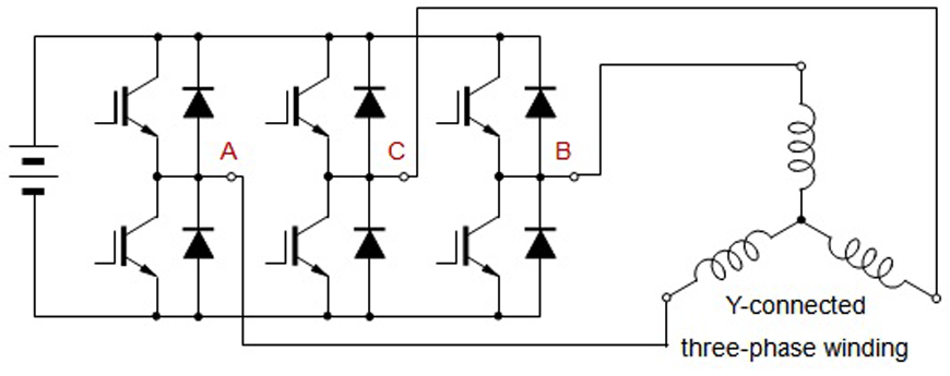
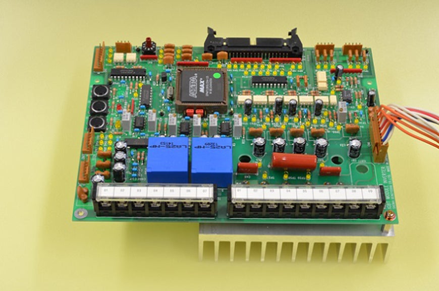
When the mechanical switches are replaced by MOSFETs or IGBTs, as shown in Fig. 7, and high-frequency PWM is employed, it is possible to produce sinusoidal alternating currents (as shown in Fig. 6(b)) instead of square-wave currents. The device configuration cannot be observed in recent inverters, but the one shown in Fig. 8 was designed for instructional purposes and allows one to see the circuit configuration. It can be seen that FPGAs, which are described below, are used to generate signals or carry out logic operations.
◇Release from complex winding operation and downsizing
Before inverters became practical, DC motors were used for operations requiring a wide speed range. Variable speed makes up a major technological area. I wrote in Volume 1 that Tesla became determined to invent a motor which does not generate sparking when he saw a DC motor producing sparks as it ran. What he invented was the AC motor, but it took nearly sixty years until it became possible to run it at variable speed.
Early tape recorders used a hysteresis synchronous motor that was either two- or three-speed to feed the tape. This motor required a complex winding.
This technology began to change immediately after the 1964 Tokyo Olympics. Today, fifty years later, we are in the age of inverters. The progress in motors used for magnetic recording can be seen in the 1/500 size reduction that has been achieved. Advances in permanent magnets also played a major role in this.
5. Expansion of digital devices
Advanced operations such as differentiation and integration are required in motor control. Since it was difficult to produce data memory functions with analog operational circuits, and because of their limitation in precision, digital computation and digital control technology were developed. The semiconductor large-scale integrated circuit (LSI) that played a major role in this area was the microprocessor. This was followed by a device called the digital signal processor (DSP). Because it carried out arithmetic operations and generated signals in a sequential manner, it was difficult to use a DSP to carry out a large number of complex processes at high speed.
The flexible programmable gate array (FPGA) was developed to fill this role. It is used to provide switching signals to devices in inverters used to drive AC and brushless motors. The microprocessor is used to manage the entire control system, small microprocessors to carry out local processing, and the FPGA to generate switching signals.
Today, there is a single-chip microprocessor dedicated to carrying out three-phase PWM drive.
6. SiC device for large power
Semiconductor technology is continuously advancing in two areas: switching functions for large currents and digital signal processing. Smooth current control is achieved by carrying out PWM at very high frequencies. This allows downsizing of external devices such as capacitors and coils, which makes it advantageous to combine the motor and electronic circuit as an integrated unit.
As we saw earlier in Fig. 4, there is no power loss when the device is completely OFF. In the ON mode, it is preferable to keep the resistance (ON resistance, RON) of the MOSFET's channel as low as possible. A device that is expected to have superior characteristics in this respect is the MOSFET in which silicon carbide (SiC) is used instead of silicon (Si). The use of SiC, which has a breakdown voltage about ten times greater than silicon, makes it possible to produce thinner semiconductor devices. This shortens the channel and thus reduces the ON resistance.
In addition, the thermal conduction of SiC devices is about four times faster than conventional silicon-based devices, which is advantageous from the standpoint of downsizing. The advantage of this technology comes into play in high-output industrial applications and traction motors for electric vehicles (EVs).
In the EV traction motor, the motor generates a high back electromotive force (emf) when operating at high speed using high-flux permanent magnets. The applied voltage must be great enough to overcome this back emf, and the switching devices and diodes in the inverter must be able to withstand this voltage. This is where SiC devices are useful, and MOSFETs and diodes with breakdown voltages exceeding 650V have been developed.
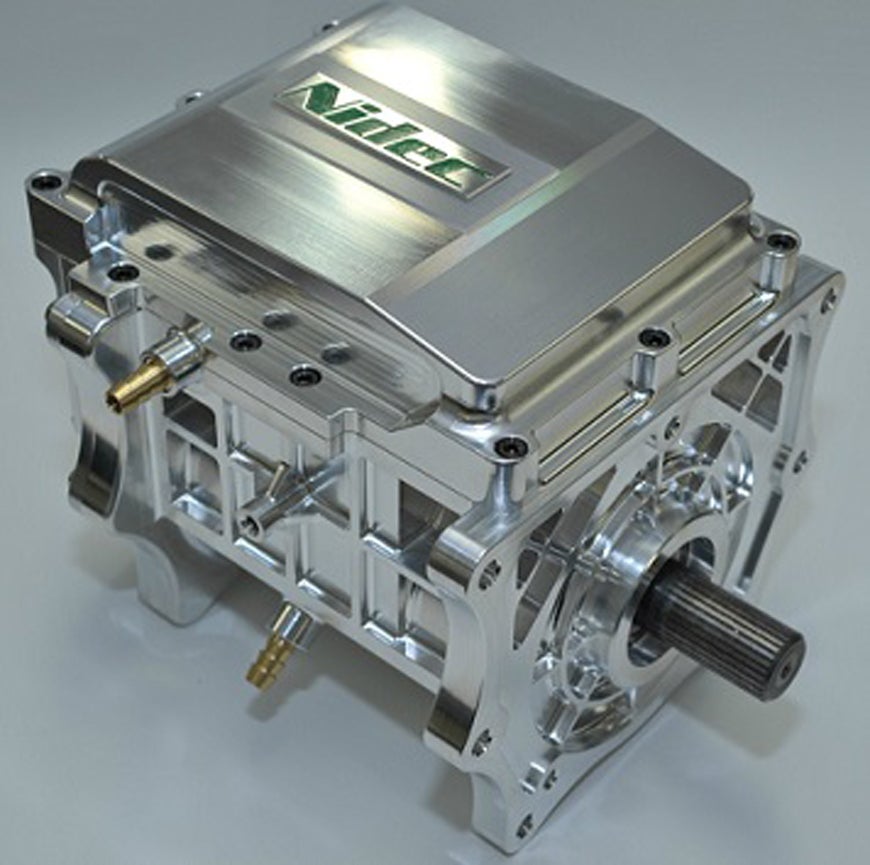
Figure 9 is a photo of a motor in which the SiC-based MOSFET circuit and motor have been mechatronically integrated into a single unit. By mechatronic integration, we mean the integration of the mechanical component, the motor, and the electronic circuitry into a single unit.
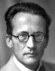
Creator of wave mechanics
Wave mechanics is the field in physics which attempts to describe quantum phenomena, which govern the behavior of elementary particles, the basic units of matter, in terms of the wave equation. In the early 1900s, when Erwin Schrödinger, the founder of wave mechanics, was a young man, a major concern of physicists was the speed of light. In Vol. 3, I wrote that Einstein proposed the Principle of Invariant Light Speed in 1905, and thus derived the elegant relationship between mass and energy.
The other major problem lay in radiation and heat. In 1900, Max Planck (1858-1947) predicted the discontinuity in the bound energy of electrons based on observations of black-body radiation. Based on Planck's quantum hypothesis, Niels Bohr (1885-1962) constructed in 1913 an electron model of the hydrogen atom by introducing the concepts of stationary states and quantum numbers, thus succeeding in providing a classical explanation to the emission spectrum with discrete energy levels. Yet, there remained unanswered questions such as why an electron close to the atomic nucleus does not spiral into the nucleus.
In 1923, ten years after Bohr's proposal, the Frenchman, de Broglie (1892-1987), proposed that particles (electrons) possess wave properties, which prepared the backdrop for Schrödinger to come onstage. During the period which saw the development of what later came to called the old quantum theory, from Plank's quantum hypothesis, Einstein's light quanta hypothesis, Bohr's atomic model, to de Broglie's proposal of matter waves, Schrödinger studied under Hasenöhrl (who was mentioned in Vol. 3) at the University of Vienna, Austria, from which he obtained his degree in 1910, and in 1921 was appointed as professor at the University of Zürich, Switzerland.
In 1926, Schrödinger announced a theory that explained the particle-like aspects of light and the wave-like aspects of particles in a unified manner, and thus broke the impasse presented by the old quantum theory. His underlying thinking to arrive at this discovery presents a mystery of sorts. The cosine and sine functions used in probability theory in statistical mechanics are wave functions. Combining this with Hamilton's principle, he discussed the probability amplitude that the electron is found at a certain position in the hydrogen atom, and thus successfully unified the concepts put forth by Einstein, Bohr, and de Broglie. The physics of wave mechanics was thus born. Schrödinger received the Nobel Prize in Physics in 1933 for this achievement. Wave mechanics was applied by Brillouin (1889-1969) in 1930 to explain the electron state in solids. This became the basis of the band theory, which is the basis of the physics underlying today's electronic engineering and semiconductors.
Around the time Schrödinger received the Nobel Prize, Hitler was persecuting Jewish academics in Germany. In 1938, during a lecture on modern physics he was giving at the University of Vienna, Schrödinger satirized the Nazi regime, as a result of which he came to be blacklisted by the Nazi party. Subsequently, he wrote a repentant confession of his changed views in which he now praised the Nazis, which was published in the newspapers, but it was too late. After being dismissed from his post, he fled Austria and went to Oxford, where he found he was not welcome after his earlier letter of confession. World War II broke out in 1939. It was de Valera (1882-1975), the prime minister of Ireland, who extended a helping hand to Schrödinger. De Valera had envisioned establishing an Institute of Advanced Studies in Dublin modeled on the one set up in Princeton. Dublin was the birthplace of William Hamilton (1805-1865), the discoverer of Hamilton's principle. Thus it was appropriate that Schrödinger, who had used Hamilton's principle to derive wave mechanics, should be appointed as the first professor of theoretical physics at the Institute. After receiving his appointment in 1940, Schrödinger spent the next decade and a half in Dublin contemplating problems in physics and beyond. He was particularly interested in the biological sciences, and his bestselling popular science book What is Life? is still viewed as a classic today.
There are many episodes involving Schrödinger and Einstein, two giants in modern physics. When Schrödinger succeeded Max Planck as Professor of Theoretical Physics at Berlin University, he became a colleague of Einstein. When the Nazi persecution of Jews began, Einstein fled to the United States to join the Institute of Advanced Studies in Princeton. The two, one in Dublin and the other in Princeton, carried on an ongoing debate through exchanged letters. One particularly interesting anecdote concerns imaginary numbers. Schrödinger attempted to apply imaginary [complex] numbers, which had been instrumental in establishing wave mechanics, to Einstein's general theory of relativity, and relayed this to Einstein. On New Year's Day of the following year, Einstein replied in a letter that "You are a smart thief (ein raffinierter Gauner)." Would this writer be going too far if he felt that this reply suggests Einstein's dislike of the use of complex numbers?
The war ended in 1945, but it was not until ten years later, 1955, that Austria was released from the government of the Allied Commission. The following year, Schrödinger returned to Vienna, where he wrote Mind and Matter (Geist und Materie), and ended his tumultuous life in 1961.