Quest For Motors' Hidden Abilities and New Potentials
Lecture 13: Induction Motor and Inductor Motor
As I explained in the 11th column, there is a wide variety of electricity-driven motors, whose torque vs. speed characteristics differ either widely or subtly from one type to another. It is not much fun to memorize motors’ types and categories – It is more important to know the meanings of and the historical background behind these names.
Despite similarities in their names, the induction motor and the inductor motor have widely different characteristics and application areas. Motor-related engineers should know that induction motors have such applications as running factories and transporting people on Shinkansen bullet trains. Still, strangely enough, not so many motor experts probably have heard about the “inductor motor.”
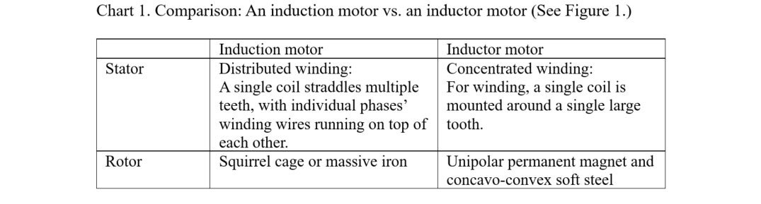
Thus, to explain differences between an induction motor and an inductor motor, see the photo of the two motors’ stators and rotors in Figure 1. I designed these motors as a training tool for aspiring motor scientists. Students may not hear about inductor motors in classes at a university even in electrical engineering department. Chart 1 draws a comparison of differences in the structures of these two types of motors.
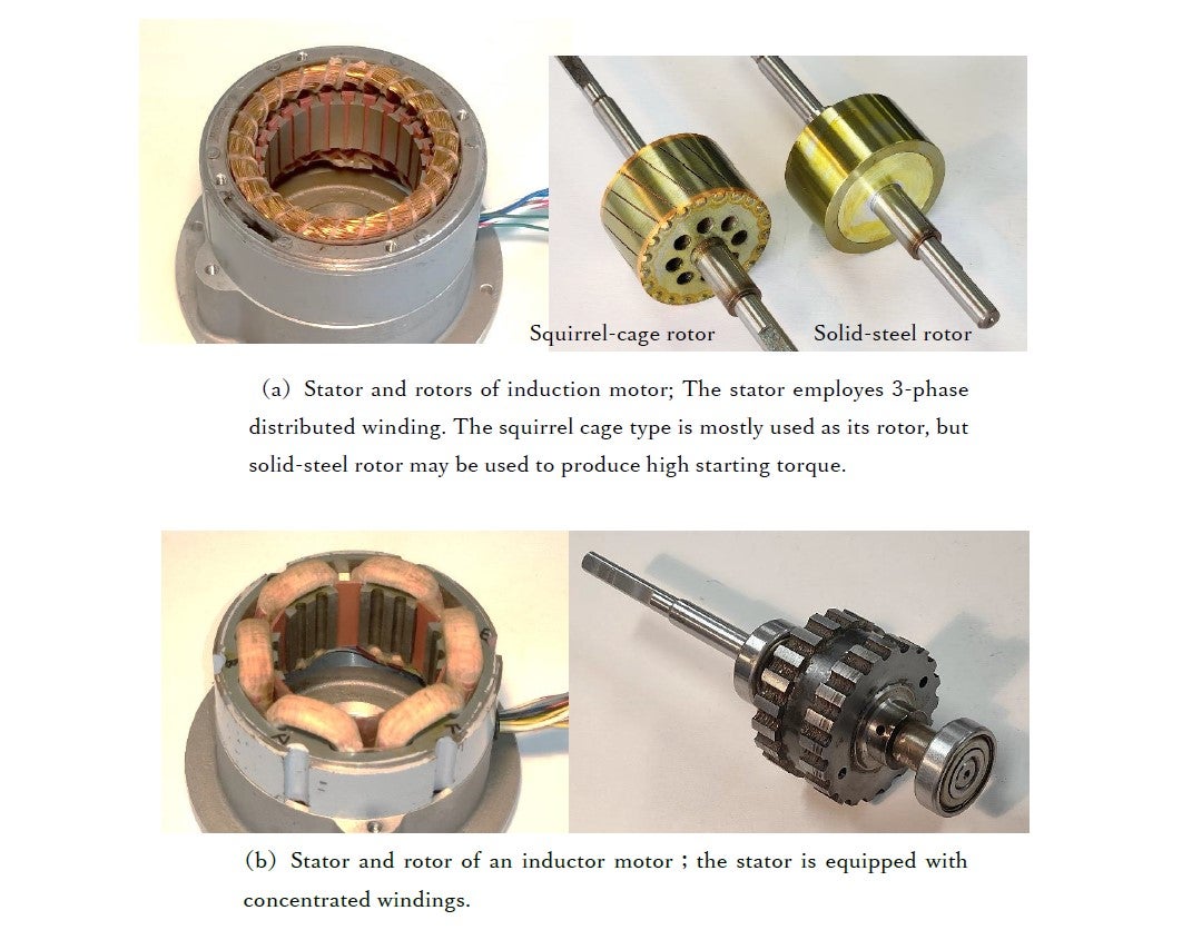
The motors in Figure 1 are both categorized as three-phase type., i.e., they are powered by three-phase alternating currents. Two-phase motors can be made as well.
The differences between “induction” and “inductor” are follows: The word “induction” refers to electromagnetic induction – the physical phenomenon that many readers probably know was discovered by Michael Faraday in 1831. It was approximately 50 years later that Nikola Tesla invented the induction motor, when he was inspired of the mechanism of two-phase alternating currents to generate a revolving magnetic field. What is an “inductor” motor then? Leaving searches for its historical roots aside, an inductor motor can, in a short sentence, be described as:
A motor to use a magneto-mechanical device to induce hetero poles from a unipolar magnetic field.
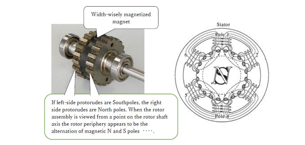
Figure 2 is provided herein to enhance the reader’s understanding of its meaning based on an axial direction-based perspective.
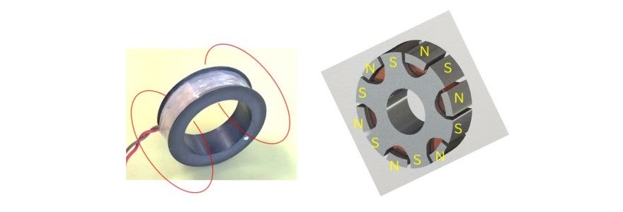
Generation of a unipolar magnetic field: Permanent magnet-type and an electromagnet-type
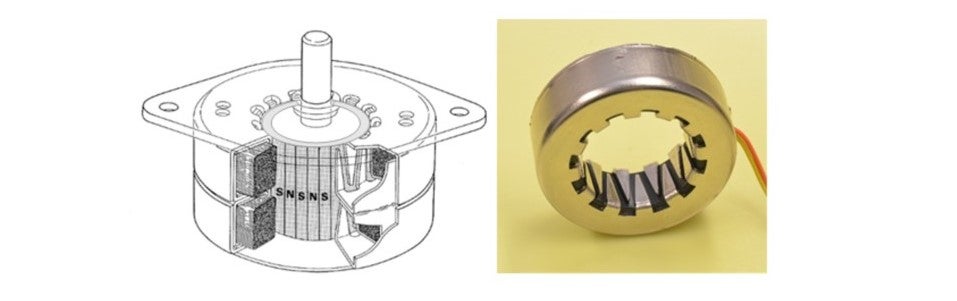
Let’s think about what a unipolar magnetic field is again. Figure 1(b) shows a rotor’s permanent magnet generating a unipolar magnetic field. On the other hand Figure 3 shows a system that uses an electromagnet. Figure 2 and3 explain principles of how a multipolar magnetic field (NSNSNSNS…) is generated not by a complex wire winding, but by the bumps and dips on the surface of steel or its claw-like shape. The figures show that an inductor can change a magnetic field’s direction by ±90°.
Two types of stepping motors
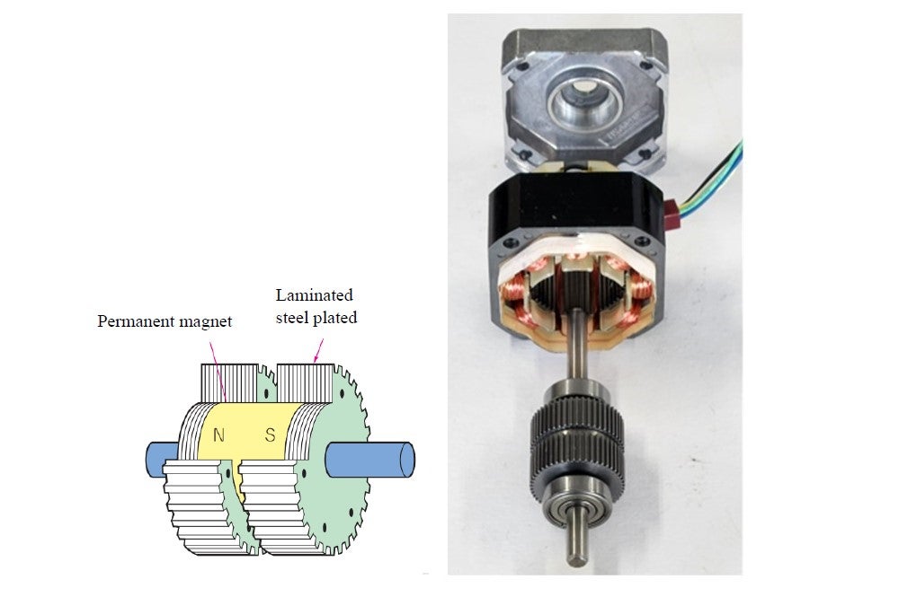
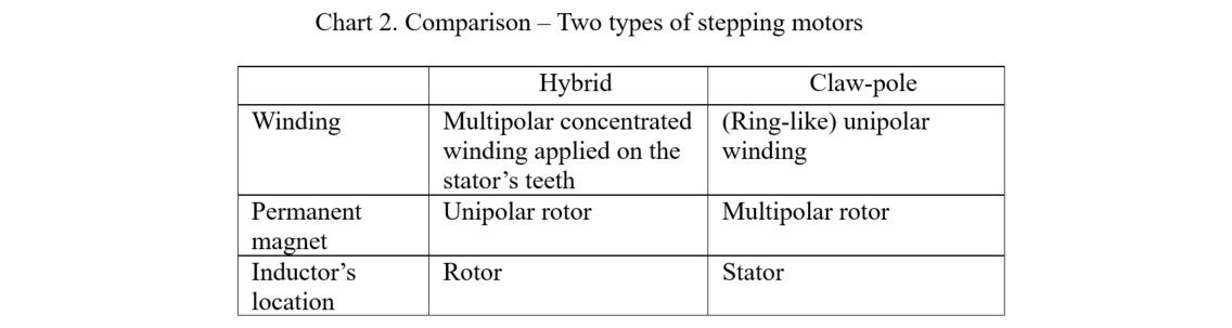
Inductor motors are mass-produced* as stepping motors for positioning control, and used in office/factory equipment, humanoid robots, etc. Stepping motors, which use permanent magnets, can be divided into hybrid-type and claw-pole-type. Figure 1(b) shows a three-phase hybrid stepping motor. A claw-pole stepping motor uses such a unipolar electromagnet as shown in Figure 3 to generate a heteropolar magnetic field via claw-pole inductors. The one shown in Figure 4 is a two-phase stepping motor or this type. Figure 5 shows an actual two-phase hybrid stepping motor used for positioning of a floppy-disk drive’s head. Chart 2 illustrates a comparison of structural differences between the two types of stepping motors. Reference 1 contains valuable information in that it discusses design details of these two types.
Relations between a motor and an electric generator
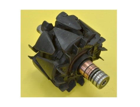
A motor can work as an electric generator as well. The alternating-current electric generator shown in Figure 6 is a typical example of an inductor machine serving as a generator in a car. With the machine in this photo, low direct-current electricity is supplied to the rotor from a battery through two slip rings, and the claw-pole inductor generates a multipolar magnetic field, with which much power is provided from the three-phase stator windings mounted outside the inductors.
The three-phase alternating-currents, which are produced in stator windings, are converted into a direct current through six rectifier diodes to be used for various electrical devices in a car. The output voltage generated as a result of this process is proportional to the engine’s rotating speed, if the electric current from the battery is kept constant. However, the direct current supplied from the battery is controlled with the speed in order to keep the output voltage independent of the engine speed.<\p>
Why the inductor motor cannot be the EV’s main motor
Among rotary motors,the claw-pole stepping motor in Figure 4 is of the simplest structure of all. With a rotation angle sensor installed, this motor can serve as a brushless DC motor. Then, if made larger, can a claw-pole motor be designed to work as a brushless motor to drive an EV? Though such an attempt is probably being made at laboratories across the globe, a product like that, mysteriously, has yet to emerge. This is most likely because of low efficiency caused by the heat loss inside the magnetic circuit. Reduction of iron losses can be a big but needed challenge.
Future possibilities for the induction motor
Induction motors are predominantly used as squirrel-cage induction motors. In the next column,I will have Professor Taketsune Nakamura of Kyoto University provide an update on the innovative and practical research on the squirrel-cage induction motor’s near future possibilities.
Reference:
1. 1. Takashi Kenjo and others: “Transistor Technology SPECIAL 165,” January 2024 edition
Chapter 15 (Sakamoto): Chapter 15: The Conventional Permanent Magnet Stepping Motor
Chapter 16 (Sakamoto): The HB Stepping Motor with Less Permanent Magnets