Quest For Motors' Hidden Abilities and New Potentials
Lecture 11: The mystery of non-Lorentz force
Nidec is recognized as a manufacturer of various types of motors. There are many types of motors, their sizes varying from small motors with a diameter of about 2mm to large motors used in hydroelectric plants.
Let me relate a scene from a session of in-house training. It was a training session on the technical aspects of motors aimed for office workers at the research institute. The instructor was an enthusiastic engineer who was in his early thirties, while the students included a competent manager who was in his early sixties. Let us call him M.
After attending the two-day program, M said “It’s curious that there are so many different types of motors, isn’t it?.” I was sitting in the same room, but to me this sounded like an expression of wonder rather than a straight question.
It has been some time since I last wrote an article for this series “Quest For Motors’ Hidden Abilities,” but it was M’s words that made me feel that I needed to write again. There are several ways I can answer this question. The answer will differ depending on what type of work the asker is engaged in. Here, I will mainly be addressing those working in motor design who have an interest in physics and math and engineers who work with motors used in automobiles. The topic is something that has not be discussed in any book in the world. The topic is “What is non-Lorentz force?”
Another reason why I thought of writing about this subject is a question raised by a young researcher who had done his thesis research on magnetic levitation. I felt that young people who are doing academic work on motors should also know what the Lorentz force is, what a non-Lorentz force is, and how they are related. This is not a basic problem but rather related to advanced mathematics and physical interpretation.
Hendrik Lorentz was a Dutch physicist (1853-1928). He became famous for the Lorentz transformations, which provided a crucial key to Einstein’s theory of relativity. I shall leave the question of what the Lorentz transformations are to a later article.
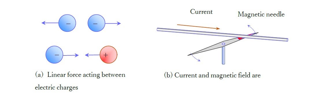
Figure 1 is often used to explain the principle of the motor that employs electricity or magnetism. Figure (a) shows how the force acts between two electric charges. Figure (b) shows the effect of electric current on a magnetic needle, known as Oersted’s experiment of 1820. Both figures show the action of forces, but (a) is a linearly acting force while (b) is a force that acts perpendicularly. When discussing the electodynamics of motors, the term “Lorentz force” is used to refer to these forces. As far as physics is concerned, this covers the basics. In geometry, which is a basic branch of mathematics, following definitions of a straight line and the normal angle, various theorems are derived from these two basic components. In comparison, the treatment of these forces is a deep and far-ranging problem from the engineering perspective of motor design and control.
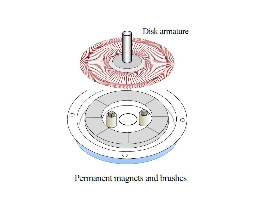
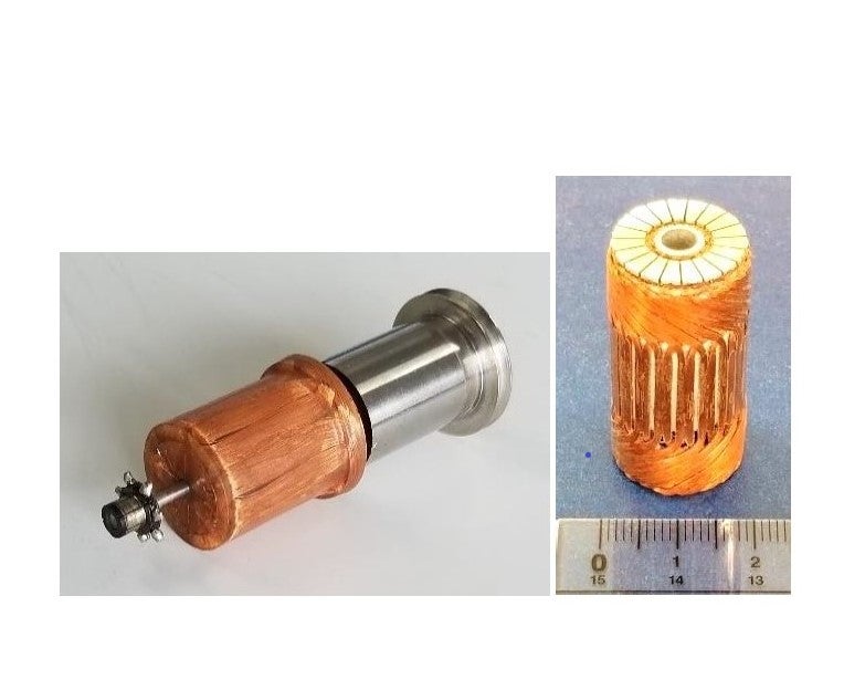
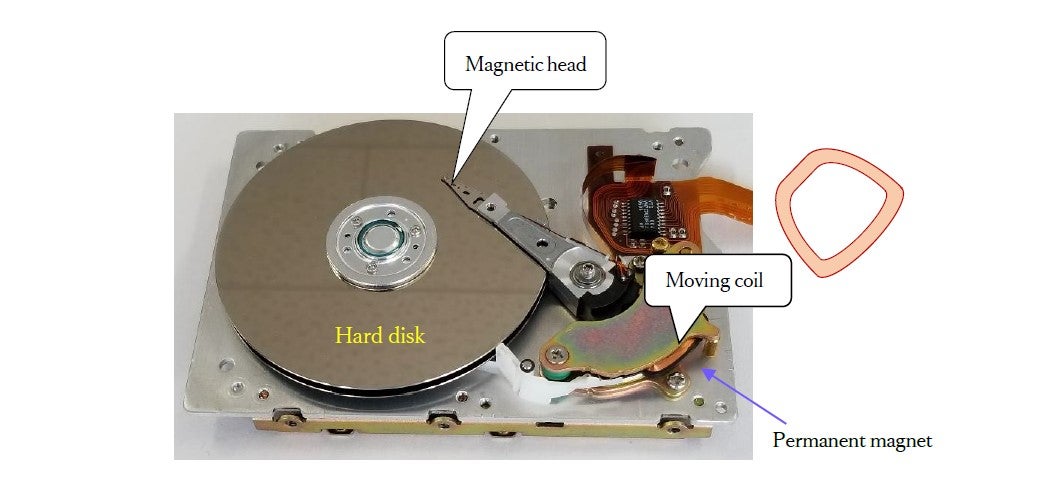
The linear principle of (a) is almost never used in motors. On the other hand, c an we say that the per pendicular principle o f (b) is often used ? The p rinted motor shown in Fig. Fig. 2, and the coreless motor, shown in Fig. 3, are examples. Another example is the moving-coil motor used to control the magnetic head in hard disk drives, shown in Fig. 4.
As these examples suggest, the motors that employ this principle fall in the category of precision motors or specialized motors, while the larger industrial motors or traction motors used for railroad and electric vehicles do not employ the Lorentz force. Motor designs that make use of the non-Lorentz force have many more applications and a much greater impact on the economy.
Quick summary of above discussion
The motor is a device that uses electricity to generate force and produce rotary motion, but very few motors use the simple straight-line vector forces like that shown in Fig. 1(a). In comparison, there are many more motor designs in which a magnetic field is incorporated to create perpendicularly acting forces. Yet, industry is propelled by a principle that goes beyond this. This is the non-Lorentz force.
Case of permanent-magnet slotted motor
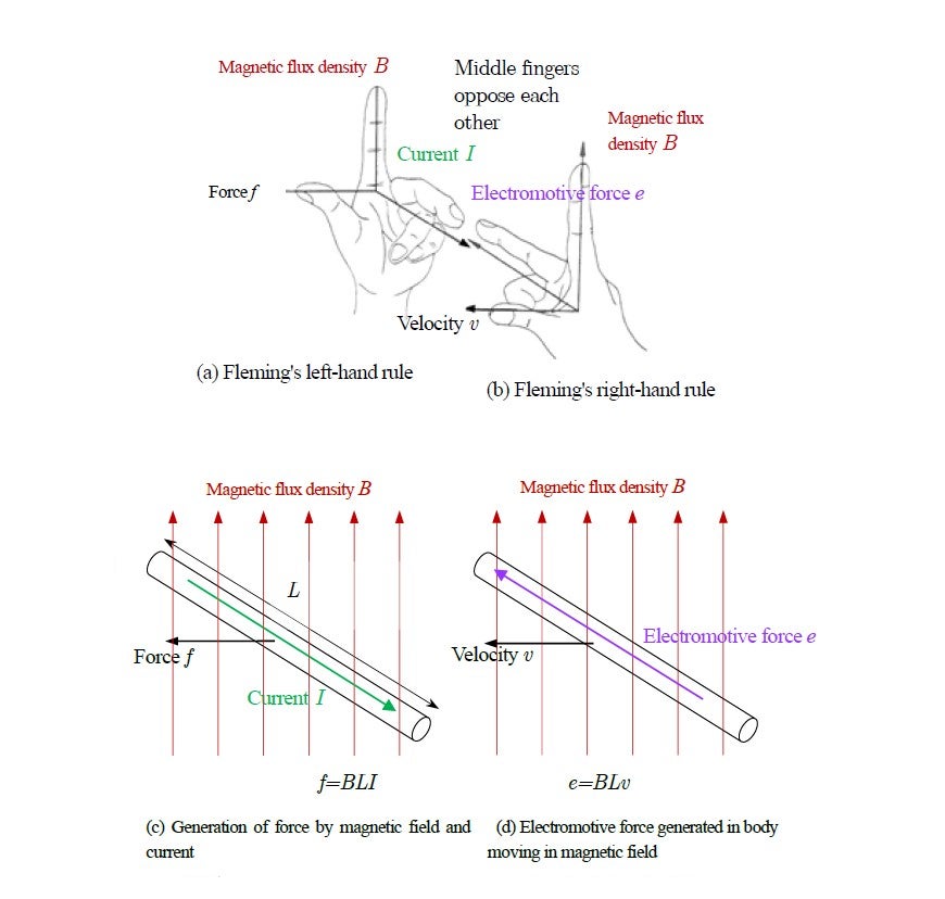
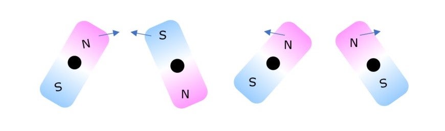
The magnetic Lorentz force appears in Fleming’s left-hand rule, known also as the BIL law, shown in Fig. 5. Torque (rotary force) can also be produced based on a different principle, i.e., from the attracton between the N and S poles of a permanent magnet, or the repulsion between N and N poles, or S and S poles, as shown in Fig. 6. Since no current is used, there is no Lorentz force in this case.
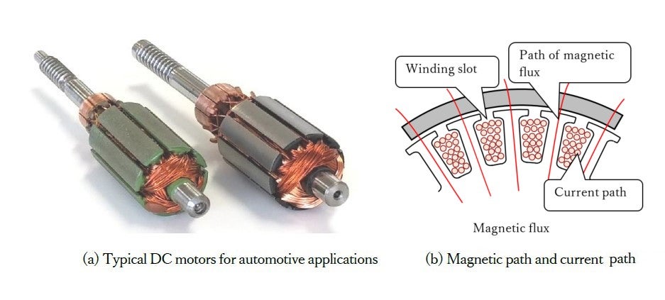
Let us go a step further. Fig. 7 (a) shows rotors of a typical DC motor. A large number of them are used in automotive applications. Fig. 7 (b) is presented to examine whether such contructions make use of the Lorentz force. As the illustration shows, no Lorentz force should be at work here.
Use of hysteresis – self-starting synchronous motor
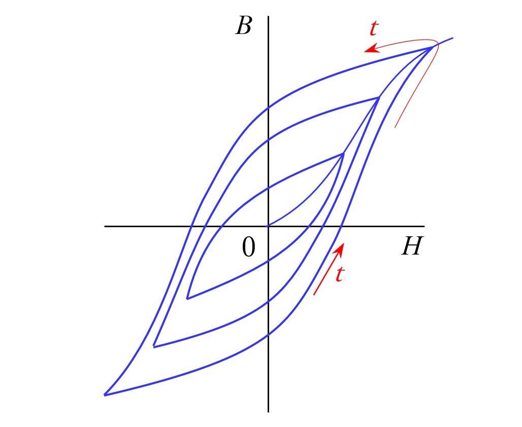
There are those who investigated further the forces produced by a motor. Instead of a complete permanent magnet, they explored the possibility of creating torque using an “incomplete” permanent magnet. This is based on the magnetic phenomenon known as hysteresis, shown in Fig. 8.
Fig. 9 is presented to examine how this applies to the motor. Fig. (a) shows the rotor of a hysteresis motor, consisting of a homogenous ring made from a magnetically semi-hard material, which cannot be a strong (complete) perpament magnet. Meanwhile, Fig. (b) shows a rotor that employs four normal permanent magnets; such rotors are used in great quantities in today’s brushless motors.
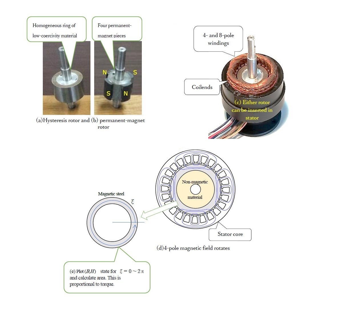
The stator houses a winding that creates a rapidly rotating magnetic field. When both rotors are combined with this stator in turn, as shown in (c), the difference of the two rotors becomes clear. The rotor of (a), consisting of hysteresis magnetic steel, fits snugly inside the stator using the 4-pole winding, and turns at the rate of 25 turns per second in Tokyo or 30 turns per second in areas west of the Fuji River, including Nagoya and Osaka. These numbers represent one-half of the AC supply frequency (50 or 60 Herz). They are one-half because the winding in this case is a four-pole winding. The stator shown in Fig. 9 (c) also houses an 8-pole winding, and when this is used the rotating speed when switched on would be 12.5 rotations per second in Tokyo and 15 rotations per second in Osaka. If a 2-pole winding is used, the rotor would turn at 50 and 60 rotations per second. A motor like this, which turns at a speed equal to the electric supply frequency divided by an integer, is called a synchronous motor. When the rotor of (b), which has four permanent magnets, is used with an 8-pole winding, no torque is produced, and this combination nannot be a motor. The same thing can be said with a 2-pole winding.
What will happen in with the combination of the (b)-rotor and with the 4-pole windings? The manent-magnet rotor can not rotate but vibrates instead. A mechanism is needed to make it start and turn, which is what the brushless DC motor provides. I shall not go into a description of this mechanism here.
From Ewing to Steinmetz
It was Steinmetz who realized that a self-starting synchronous motor can be produced by using a weak (imcomplete) permanent magnet. This was around 1920. However, it was the Scottish engineer-scientist, James Ewing (1855-1935), who was recruited by the Japanese government to teach in Japan, who realized the importance of hysteresis and coined the word. This was in 1882, when he was a professor at the Imperial College of Engineering (Kobu Daigakko; forerunner of Faculty of Engineering of the University of Tokyo). Why were capable Japanese engineers who trained under him unable to invent the hysteresis motor? This is a case that shows that the ability to comprehend and remember and the ability to create or invent new things are quite different things.
Teare’s torque equation
It was Teare (B. R. Teare, 1907-1987) who took Steinmetz’s discovery of the principle one step further to construct a theory that led to practical applications. In 1940, he presented the mathematical expression for non-Lorentz force in a readable article in the Transactions of AIEE (American Institute of Electrical Engineers). He did not use the term non-Lorentz force, however. His paper exerted a decisive impact on the progress of tape-recorder motors (Teare’s contribution is briefly discussed in an earlier article).
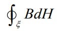
Teare’s torque equation was expressed as in Fig. 10, but it can be written in a more compact way as follows.
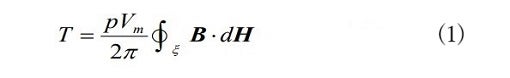
The key here is the integral ![]() .
.![]() is the volume of the magnetic material, and
is the volume of the magnetic material, and ![]() is the number of poles of the stator winding.
is the number of poles of the stator winding.

In 1964 I received this paper from an executive of a certain compay when I was 24 years old. I knew that ![]() expressed the loss due to hysteresis, and being young and having a fairly flexible mind, I realized that the fact that the loss and output can be expressed in a similar format by changing the parameter was somehow related to the theory of relativity (spacetime unity). I had, of course, taken courses in mathematics, physics and electromagnetism in my undergraduate days and received further mental training during my master’s program.
expressed the loss due to hysteresis, and being young and having a fairly flexible mind, I realized that the fact that the loss and output can be expressed in a similar format by changing the parameter was somehow related to the theory of relativity (spacetime unity). I had, of course, taken courses in mathematics, physics and electromagnetism in my undergraduate days and received further mental training during my master’s program.
Two years later, I met a mathematician named Yasujiro Nagakura, who taught me that this integral is called the Stieljes integral and that it is related to the Riemann integral. It was then that an idea flashed into my mind. I realized that Teare’s equation is not limited to magnetic hysteresis, but must apply to all motors.
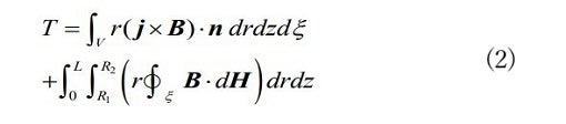
I attempted to explain this using the theory of Poynting, an English physicist who had worked under Maxwell, and the volume integral theorem of the German mathematician Gauss. The outcome was that I derived the following torque equation.
Given an arbitrary vector ![]() , the following relation holds.
, the following relation holds.
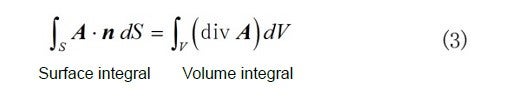
This theorem can be used to replace the surface integral in vacuum with the volume integral of the rotor.
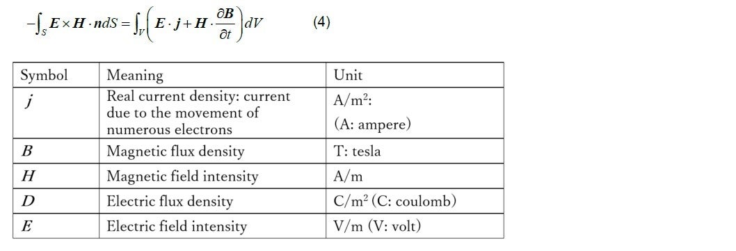
Let us say that the arbitrary vector A is given by ![]() is given by
is given by ![]() (Poynting vector). Using Maxwell’s equations, we obtain the following expression.
(Poynting vector). Using Maxwell’s equations, we obtain the following expression.
Using the following technique in calculus
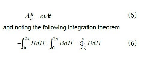
we remove ![]() from the time differential
from the time differential ![]() and examine
and examine ![]() . Paying attention to
. Paying attention to ![]() in the volume integral, we obtain
in the volume integral, we obtain ![]() .
.
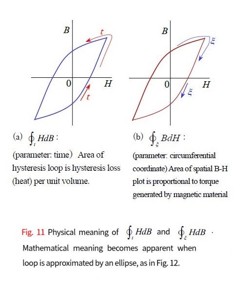
As shown in Fig. 11(a), the area of the ![]() hysteresis curve plotted by tracing time expresses a type of iron loss, but the area of the
hysteresis curve plotted by tracing time expresses a type of iron loss, but the area of the ![]() plot obtained by tracing space at a given moment in time, shown in (b) and Fig. 9(e), expresses the torque, which multiplied by the angular velocity
plot obtained by tracing space at a given moment in time, shown in (b) and Fig. 9(e), expresses the torque, which multiplied by the angular velocity ![]() is power. As this shows, power is mathematically computed by a geometrical operation on the (
is power. As this shows, power is mathematically computed by a geometrical operation on the (![]() ) plane. Fig. 12 shows the mathematical meaning from another perspective.
) plane. Fig. 12 shows the mathematical meaning from another perspective.
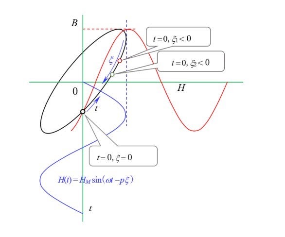
 lags behind
  in time.
I shall describe some other related and interesting facts. The first is what happens when the above theory is applied to induction motors, and the second concerns the mystery of the claw-pole stepping motor.
Case of induction motors: Comparison with Lorentz force
Use of electromagnetic non-Lorentz force
We shall now examine non-Lorentz forces. In terms of economic output, perhaps 99 percent of motors employ non-Lorentz forces, although I have not encountered a technical book which treats this subject from the engineering point of view. Investigation of this will revolve on the meaning of the integral ![]() .
.
When I derived (2), the classical theory of equivalent circuits for induction motors provided me with a major hint. This is a computational method that elegantly correlates the magnetic circuit inside a motor with the AC circuit. It employs the concept of secondary input. What I did was to reexamine this concept using Poynting’s theory of electromagnetic energy. I introduced the special theory of relativity to the treatment of slip in the induction motor.
Applying Poynting’s energy flux, the energy transported by ![]() is all converted to Joule heat when there is no moving body in the system. However, we must be careful here. Einstein’s assertion
is all converted to Joule heat when there is no moving body in the system. However, we must be careful here. Einstein’s assertion
“The general laws of nature are to be expresses by the equations which apply to all coordinate systems.‥‥‥”
can be slightly overstating the case. If someone were to assert that the energy flowing into a body expressed by the Poynting vector ![]() is converted to heat in any coordinate system, I will have to object. Reconsidering the energy conservation law, I built a theory based on the realization that the electromagnetic energy transmitted in a vacuum should be converted to mechanical energy as well.
is converted to heat in any coordinate system, I will have to object. Reconsidering the energy conservation law, I built a theory based on the realization that the electromagnetic energy transmitted in a vacuum should be converted to mechanical energy as well.
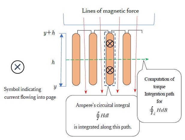
The rotor core of the induction motor has a cross section like the one shown in Fig. 13. The slots are filled with aluminum or copper, and provide the passage for current. However, the magnetic flux passes through the iron core. Therefore, the conductors are not subjected to Lorentz force. Yet, torque is produced by the output shaft. In other words, some force must be acting on the armature core.
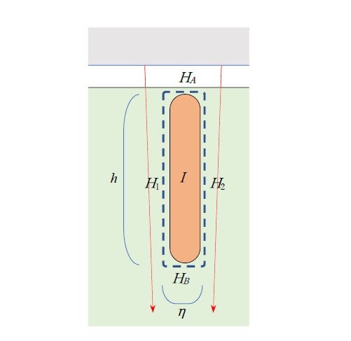
Fig. 13 shows two integration paths. The broken horizontal line represents part of the integration path for torque calculation, shown in Fig. 9(e). The other one is a circuital path for Ampere’s circuital integration ![]() . This is redrawn (for a closed slot construction) in Fig. 14. The integral law can then be written as
. This is redrawn (for a closed slot construction) in Fig. 14. The integral law can then be written as
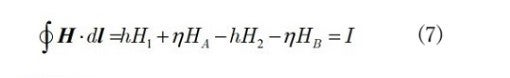
where ![]() and
and ![]() are the horizontal components of the magnetic field intensity which we assume to be neglible, so that we obtain simply
are the horizontal components of the magnetic field intensity which we assume to be neglible, so that we obtain simply

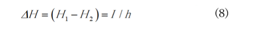
Thus, the difference of ![]() at the two sides of the slot,
at the two sides of the slot, ![]() at the two sides of the slot,
at the two sides of the slot, ![]() , is proportional to current I, or
, is proportional to current I, or
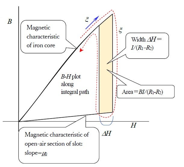
We next compute ![]() shown by the horizontal line in Fig. 13 A trace of the(
shown by the horizontal line in Fig. 13 A trace of the(![]() ) A trace of the Fig. 15. The area enlosed by the loop is computed from the area of the hatched trapezoid, given by
) A trace of the Fig. 15. The area enlosed by the loop is computed from the area of the hatched trapezoid, given by ![]() . Integrating this from
. Integrating this from ![]() to
to ![]() and in the conductor’s length direction, the non-Lorentz force is found to be
and in the conductor’s length direction, the non-Lorentz force is found to be ![]() . In other words, it is the same as the Lorentz force. The latter force would act on the conductor if the magnetic flux went through the conductor, but not if the flux passes the core and not the slot. In other words, the force acts on the iron core but we cannot know exactly where it acts from this mathematical operation. We can verify it as the shaft’s torque output.
. In other words, it is the same as the Lorentz force. The latter force would act on the conductor if the magnetic flux went through the conductor, but not if the flux passes the core and not the slot. In other words, the force acts on the iron core but we cannot know exactly where it acts from this mathematical operation. We can verify it as the shaft’s torque output.
 : taken around a single slot
One of the mysteries here is the importance of the iron core. It would be difficult to construct a sufficiently sturdy motor that does not employ an iron core that readily passes magnetic flux, but still employs Lorentz force. This property of iron derives from the electrons’ spin. Einstein was one person who showed an interest in spin. Together with the Dutch physicist, de Haas (who was Lorentz’s son-in-law), he conducted an experiment in the winter of 1915 to confirm that the magnetic moment created by spin can be converted to mechanical momentum. However, spin only began to be understood when quantum mechanics was being developed, and it was only in 1928 that the English physicst, Paul Dirac (1902-1984), published a decisive paper on the subject. Using brilliant mathematical manipulation, he derived the spin quantum number.
Case of permanent-magnet stepping motor that uses claw-poles
While there are many types of motor constructions, the claw-pole motor, shown in Fig. 16, presents a puzzle. The torque can be theoretically explained by setting up the integration path properly in relation to the teeth. However, a puzzle appears when analyzed in more depth. Among the wide variety of motor constructions, none is as simple and economical as the winding of the claw-pole stepping motor. Other motors have coilends as seen in the photo in Fig.9, which are uneconomical portions of windings and present problems in the winding fabrication process.
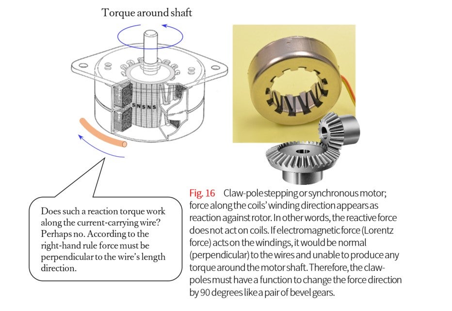
What this writer finds mysterious is the function of the claw poles which change the direction of force by 90 degrees. In the left-hand rule, corresponding to the BLI law, the current-carrying conductor and electromagnetic force are perpendicular to each other. The bobbin-type coils of the claw-pole motor create a three-dimensional magnetic structure that changes the direction of force by 90 degrees in the manner of a bevel-gear as shown int this figure. This is none other than the mysterious workings of non-Lorentz forces. It may be worthwhile to reexamine Fleming’s left- and right-hand rules to explore the mysteries of electrodynamics. This is a fundamental problem (i.e., related to spacetime) which is not taught at universities.
Conclusion
We saw that the non-Lorentz force is deeply related to the properties of iron. Iron has a profound significance. In terms of physics, this comes down to the issue of electron spin. To answer M’s question properly, it would be necessary to discuss motors in relation to semiconductor electronics, which in itself would require several books. Motor technology may in the future become a part of spintronics, which is an emerging engineering discipline that overlaps with electronics. Shifting our perspective, this issue may be construed as a message to the ferrous-metal industry. This may be of interest to those working in business adminstration or corporate management strategy.
1. B.R. Teare : Theory of hysteresis-motor torque, AIEE, 1940, p.907-12