Quest For Motors' Hidden Abilities and New Potentials
Lecture 16: The Structures and Types of Synchronous Motors
As explained at the beginning of the 11 th lecture, there is a mysteriously great variety of motors. Based on the types of their electric power supplies, motors used to have been classified into only two categories: DC (direct current) or AC (alternative current), and there was a notion that AC motors can further be divided into commutator type and rotating-field type. The rotating-field type can be further divided into:
◆ Synchronous motor, and
◆ Induction motor
Note that German articles and papers refer to an induction motor as Asynchronmotor rather than Induktionsmotor or Induktionsmaschine .
As I have already lectured on the induction motor, I will focus on the synchronous motor this time. Based on the types of their drive methods synchronous motors can be broadly divided into:
◆ Self-starting types, i.e. , motors designed to start when connected to a 50/60Hz commercial power supply, and reach the synchronous speed; and
◆ Electronically kicked-off types, i.e. , motors that capture information on the rotor’s rotating angle, and is started and accelerated by the electronic circuit.
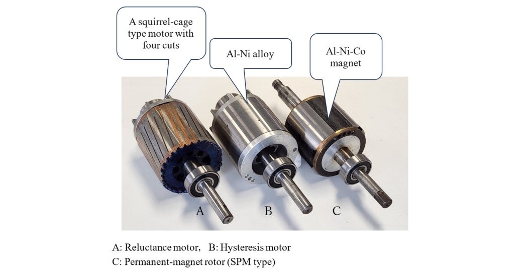
See the photos in Illustration 16-1 . The self-starting type possesses similarities with the induction machine in appearance, and can be divided into two sub types, depending on their rotor’s structure and the nature of its materials.
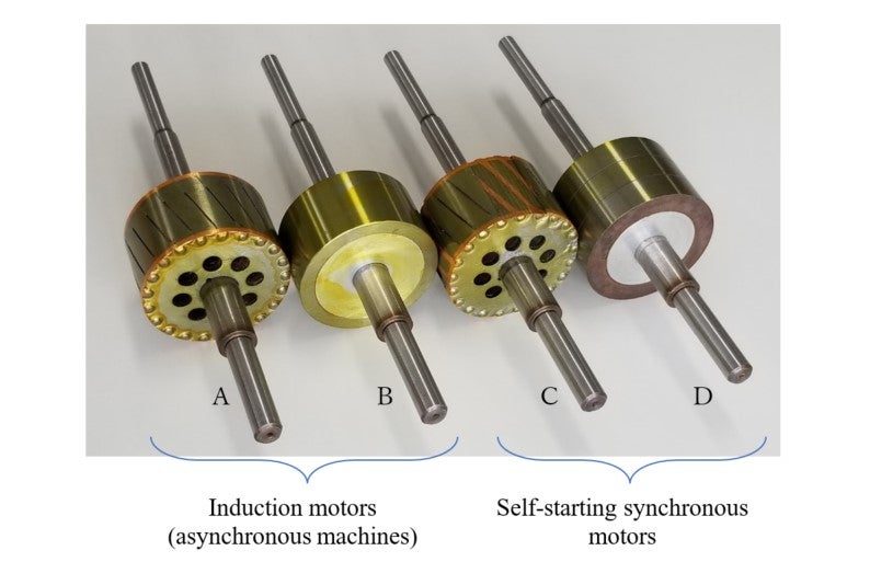
A: Squirrel-cage rotor
B: Solid-steel rotor
C: Salient-pole squirrel-cage (Reluctance motor)
D: Hysteresis motor
Reluctance Motor
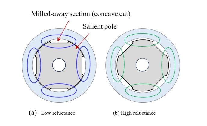
Illustration 16-2 depicts a cylindrical rotor with four concave cuts to form a salient-pole type rotor. It is easier for the four-pole magnetic flux to pass through the four mechanical salient poles as shown by blue paths in (a); whereas it is difficult for the green flux to do so as shown in (b). The degree of difficulty for magnetic flux to go through a material is called reluctance . (The degree of difficulty for an electric current to pass through a wire is called a resistance .)
When an action (magnetomotive force) is generated by winding currents, which option, (a) or (b) above, will nature select? The answer is (a), where more magnetic flux flows. When a magnetic flux pattern rotates, you can make a synchronous motor work if you can maintain this favorable condition. Therefore, by combining a convex-pole structure like this with a squirrel-cage conductor structure, the motor will start, gather speed, and enter the synchronous running mode. This is type C and called a “reluctance motor.” This photo shows a finished squirrel-cage rotor (A) with shallow concave grooves. However, the load must not be excessive.
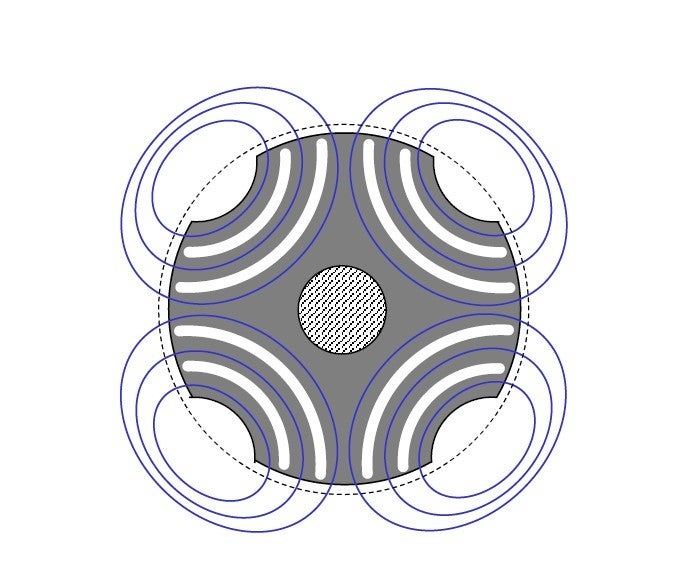
Illustration 16-3 depicts a cross-section with flux barrier pores to ensure an arrangement for a smooth magnetic passage.
In reality, it is important to ensure that the motor can start to run and works with high efficiency for specific applications. This is why the flux barrier’s shape must be adjusted appropriately.
From the eddy-current motor to the hysteresis motor
Rotors A and C in
Illustration 16-1
are for an asynchronous motor and a synchronous motor respectively, and they have different cross-sectional structures. The next issue is the similarities and differences between Rotors B and D in
Illustration 16-1
. The structure of Rotor B, made of regular iron, is the simplest of all rotors. Unlike Rotor A (squirrel-cage type), which has paths for magnetic flux and those for electric currents; whereas, in
Rotor B, which is made of iron, both magnetic flux and current run. This rotor is called a “solid-steel rotor” or an “eddy-current type.” Its
![]() characteristics, when adopted to a squirrel-cage type rotor, are similar to those when
characteristics, when adopted to a squirrel-cage type rotor, are similar to those when
![]() is large in the previous illustration of 14-7. That is, the starting torque is high, and the torque decreases with speed. In regular iron, the magnetic coercive force (
is large in the previous illustration of 14-7. That is, the starting torque is high, and the torque decreases with speed. In regular iron, the magnetic coercive force (
![]() ) is very low. Instead, Rotor D uses an alloy that becomes a moderate
) is very low. Instead, Rotor D uses an alloy that becomes a moderate
![]() . “Moderate
. “Moderate
![]() ” means that the alloy is unlikely to become a permanent magnet, and such a material is sometimes referred to as “semi-hard steel.” Roughly, magnetic steel can be divided into the following three
types:
” means that the alloy is unlikely to become a permanent magnet, and such a material is sometimes referred to as “semi-hard steel.” Roughly, magnetic steel can be divided into the following three
types:
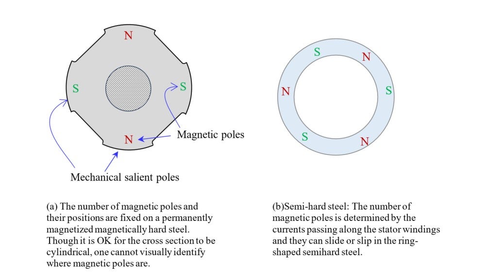
◆ Magnetically mild steel: Iron with weak magnetic coercive force;
◆ Magnetically hard steel: Magnetic steel with high magnetic coercive force for permanent magnets; and
◆ Semi-hard steel: Magnetic steel with moderate magnetic coercive force.
The semi-hard steel demonstrates a curious character as a rotor, which is kwon as the hysteresis motor.
What is hysteresis
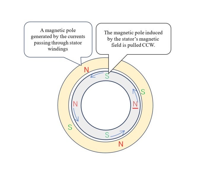
In a hysteresis motor, the magnetic poles (N and S) generated by the electric current flowing through stator winding induce the reverse poles (S and N) on the cylindrical rotor steel. Now note that
the stator’s magnetic field is rotating; now CCW (counterclockwise). As shown in
Illustration 16-4
, the indued magnetized pattern on the rotor surface is sliding also in CCW keeping a slight distance to the stator’s rotating field. Owing to this distance a CCW torque is generated on the rotor.
Stator’s N S N S pattern is pulling rotor’s S N S N pattern.
Illustration 16-5
shows this phenomenon as a
![]() relationship on a single point inside the rotor ring steel. This is known as hysteresis. In the illustration, the horizontal axis represents the magnetic field strength (
relationship on a single point inside the rotor ring steel. This is known as hysteresis. In the illustration, the horizontal axis represents the magnetic field strength (
![]() ), and the vertical axis is the magnetic flux density (
), and the vertical axis is the magnetic flux density (
![]() ).
).
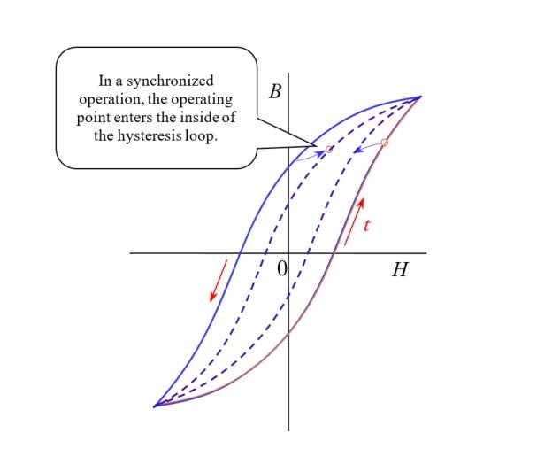
(Details, including space-time relations, are provided in the 11 th lecture.)
The surprisingly simple equivalent circuit to analyze the hysteresis motor that requires materials with very complex magnetic properties
In hysteresis, the relation between
![]() and
and
![]() is not linear like
is not linear like
![]() instead, it is as depicted
Illustration 16-5
, with (
instead, it is as depicted
Illustration 16-5
, with (
![]() ) taken into consideration. Many books claim that, after a cycle of changes in the (
) taken into consideration. Many books claim that, after a cycle of changes in the (
![]() ,
,
![]() ) operating point, the hysteresis loop has gone through a round, and that heat is generated, being proportional to the loop area. Let’s not believe this information as it is described: Instead, we
shall doubt the claim’s validity to unlock this motor’s mysteries.
) operating point, the hysteresis loop has gone through a round, and that heat is generated, being proportional to the loop area. Let’s not believe this information as it is described: Instead, we
shall doubt the claim’s validity to unlock this motor’s mysteries.
◆ The aforementioned claim may make sense if the rotor is at a standstill.
◆ But what if it is rotating?
The best way is probably to calculate the temporal alteration of
![]() and
and
![]() on the coordinate system that rotates with the rotor to make a formula for thermal loss (
on the coordinate system that rotates with the rotor to make a formula for thermal loss (
![]() ). Let’s, for example, examine the case of Kyoto’s synchronous frequency (60Hz). If the rotor is at a standstill, the amount of heat loss unit volume will be 60 times the hysteresis loop area. Let’s
suppose this amount is 60W. However, if the rotor’s rotating speed reaches 20 turns per second, the energy loss per second in the rotor will be 60 – 20 = 40 watts; this means that 2/3 of the amount
from the above case has been consumed as heat.
). Let’s, for example, examine the case of Kyoto’s synchronous frequency (60Hz). If the rotor is at a standstill, the amount of heat loss unit volume will be 60 times the hysteresis loop area. Let’s
suppose this amount is 60W. However, if the rotor’s rotating speed reaches 20 turns per second, the energy loss per second in the rotor will be 60 – 20 = 40 watts; this means that 2/3 of the amount
from the above case has been consumed as heat.
◆If the cylindrical rotor is beautifully machined and polished, it is probably impossible to visually determine that the rotor is rotating or stationary. However, as the changes in magnetic field
intensity
![]() are subject to the current in the stator windings which are stationary, the
are subject to the current in the stator windings which are stationary, the
![]() /
/
![]() changes may still seem to be 60 Hz even with a rotor on a coordinate system at rest. Specifically, let’s think differently and say that, every second, a 60Wof energy is injected from the winding into
the rotor via a gap (and not consumed by the rotor). What is the difference between the injected electricity (
changes may still seem to be 60 Hz even with a rotor on a coordinate system at rest. Specifically, let’s think differently and say that, every second, a 60Wof energy is injected from the winding into
the rotor via a gap (and not consumed by the rotor). What is the difference between the injected electricity (
![]() ) and loss (
) and loss (
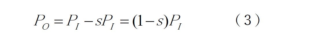
![]() )? Could it be the mechanical output (
)? Could it be the mechanical output (
![]() ) in the formula below?
) in the formula below?

In this scenario, let’s raise an import hypothesis and interpret, “In the motor, electric power (
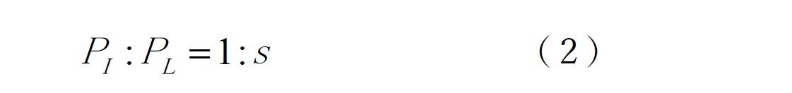
![]() ) flows from the stator into the rotor via the gap.” The technical term for this power flow is “secondary input.” The ratio of the input
) flows from the stator into the rotor via the gap.” The technical term for this power flow is “secondary input.” The ratio of the input
![]() to loss
to loss
![]() can be given in terms of slip
can be given in terms of slip
![]() as:
as:
From these two formulae we obtain:
Then, based on the output vs. torque relation we get
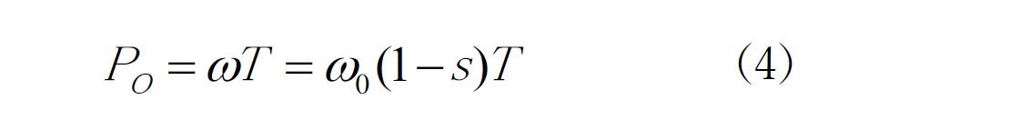
From (3) and (4) the amount of torque will be:

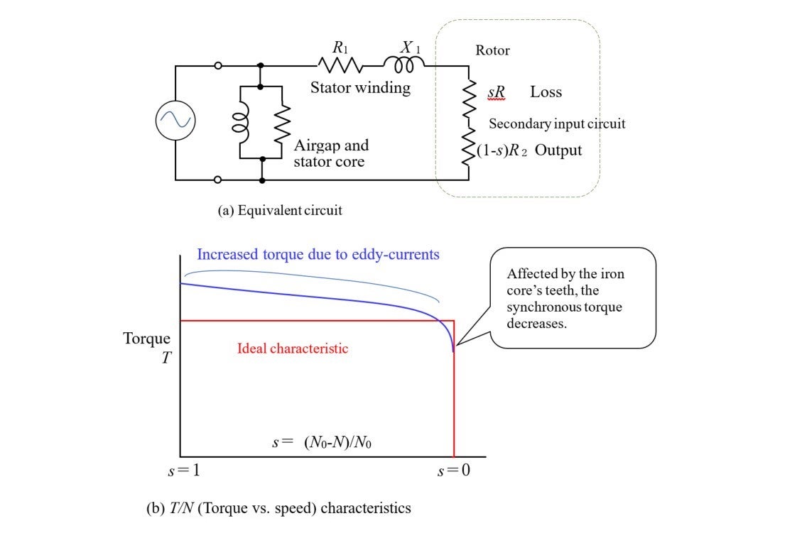
As we saw in the previous lecture, the above laws can be expressed by means of an equivalent circuit shown in
Illustration 16-6
. This circuit diagram captures and explains the essence of the motor phenomenon. Unlike a case with a squirrel-cage type induction motor, the secondary circuit’s resistance (
![]() ) that corresponds to the rotor becomes a constant value irrelevant to the slip (
) that corresponds to the rotor becomes a constant value irrelevant to the slip (
![]() ) in hysteresis motor. When this
) in hysteresis motor. When this
![]() is divided into s: s-1 in ratio,
is divided into s: s-1 in ratio,
![]() orresponds to loss, while
orresponds to loss, while
![]() represents output, while torque would be constant, regardless of
represents output, while torque would be constant, regardless of
![]() . This means that both current and torque remain unchanged from the start to synchronous operation.
. This means that both current and torque remain unchanged from the start to synchronous operation.
The parameters in this circuit are irrelevant to
![]() , and so, under a fixed voltage, the secondary input (
, and so, under a fixed voltage, the secondary input (
![]() ) is constant independent of rotational speed. This means that torque
) is constant independent of rotational speed. This means that torque
![]() is constant independent of speed as well.
is constant independent of speed as well.
Thus, by using a semi-hard steel in place of a squirrel-cage structure, one can make a motor that can start, accelerate and eventually reach the synchronous speed by simply connecting the winding terminals to an alternating power source. As explain in the 11 th lecture, it was Teare who provided an excellent explanation on hysteresis-caused torque phenomena by using geometric mathematics.
The differences between the electromagnetic induction and the phenomenon where a magnetic pole is induced by a magnetic field alone to a nearby magnetic steel also appear on an equivalent electric
circuit as the difference in secondary resistance
![]() . This is a mystery in the motor science
. This is a mystery in the motor science
Illustration 16-6(b) explains that, in reality, torque decreases as the synchronous running starts. It was also Teare who accurately explained that this phenomenon is due to the effects of the teeth of the stator’s iron core. Based on some experiments and calculations by myself, I realized that the medium to support the hysteresis ring must be a non-magnetic body such as zinc or aluminum.
As you saw so far, self-starting synchronous motors can be divided into reluctance motors and hysteresis motors. It was the latter that was manufactured in large quantities for tape recorders, an IT device. It was primarily because the hysteresis motor has a uniform structure to prevent torque ripples.
How this motor came to be mass-produced is interesting when seen in connection with the popularization of tape recorders and the firm foundation of small electric motor industry. However, the reason for the hysteresis motor’s rapid decline is that, around 1970, the limitation of wow-flutter level of this motor when used in the rotating head of video recorder became apparent. Smaller, more efficient brushless DC motors, which employs a permanent magnet like (a) in Illustration 16-7 , began to be manufactured to replace hysteresis motor. This illustration shows a clear difference in application between the semi-hard steel the magnetically hard steel.
Further, Illustration 16-8 shows an example of three basic-type synchronous motors made based on the same, stator-sharing dimensions.
The brushless DC motor: A motor that uses an electronic circuit
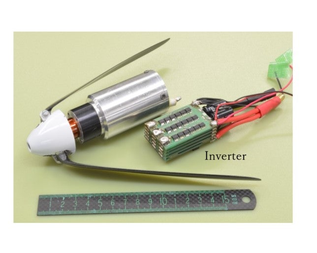
To operate an AC motor, instead of using commercial power supply, one can convert the power into direct current (DC), and reconvert it into AC (with voltage and frequency available for free use), to rotate the motor. The EV (electric vehicle) is a typical example of using a battery as a DC power source. In such a case, one must control not only the frequency of alternating volage and electric current but its phase as well. The electronic circuit that can perform all of these tasks is called an “inverter,” the name that indicates a device to perform a reversal, DC-to-AC conversion as opposed to the AC-to-DC conversion device (converter).
Illustration 16-9 shows a symbolic brushless DC motor and inverter which produced a world championship in the electric plane race known as the F5B race. Its rotor employed four pieces of neodymium magnet in a standard SPM construction. The IPM version is used for mid and large-size applications.
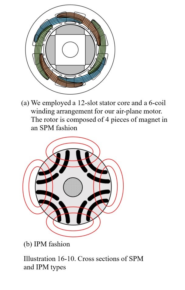
● SPM (surface permanent magnet) type
This type, which is officially called the “surface permanent magnet type,” is a motor with permanent magnets arranged so that they can be seen from the outside. Illustration 16-10(a) shows cross-section to be used in our airplane motor.
●IPM (interior permanent magnet) type
This type has permanent magnets buried in its rotor. The basic style of flux barriers shown in Illustration 16-3 can place curved permanent magnets. Magnetic flux from these magnets can flow smoothly as shown in Illustration 16-10 . The blue magnetic flux in Illustration 16-3 is due to the stator’s currents. The combination of these flux sources is the mainstream of the current permanent magnet motors for EVs.
For the 17 th lecture
The next lecture will feature the superconducting motor that utilizes the squirrel-cage-type induction motor’s structure. The 14 th and 15 th lectures featured the induction motor as part of the preparations for the 17 th lecture, and this 16 th lecture featured the structure of the synchronous motor, for us to understand these motors’ connections to the superconducting motor. Surprisingly, it shares similarities with the aforementioned hysteresis motor. This is another mystery surrounding motors.