Quest For Motors' Hidden Abilities and New Potentials
Lecture 17:The Superconductor Induction Motor
Introducing the Lab of Professor Nakamura at Kyoto University
Motors exist in a wide variety of types, as I dwell in this series of topics on mysteries about motors. This is why we constantly discuss how to select, drive, and control the right motor for applications. Selecting the right motor, though, is not so easy. Take motors to drive electric vehicles, for example. Selecting such motors has been an issue for the past 50 years or more, but the present world of motor science does not seem to have identified the best motor for that purpose yet. The same holds true for electric airplanes. Identifying the right motor to drive them is a classic yet new topic.
What if we adopt superconductivity, a state-of-the-art technology? To answer this question, I set an interview with Professor Taketsune Nakamura at Kyoto University, who is one of the experts in this area.
Nakamura: As Program-specific Professor, I’m in charge of the laboratory donated by Nidec Corporation. In this lab launched on April 01, 2017, I work on a variety of topics, including clarifying the basic electromechanical energy conversion process, optimization design, control technology, and systemization, mainly for rotary machines. For these researches, we use various magnets, magnetic materials, and conductive materials including superconducting ones.
Kenjo: I imagine that superconductivity can be applied to a motor in various ways. Especially interesting is the use of superconductor materials for the squirrel-cage rotor of an induction motor.
Nakamura: First of all, a superconducting motor must be cooled to a cryogenic temperature to operate it. Therefore, it is important to minimize cooling costs, and this is why R&D was focused on high-temperature superconducting (HTS hereafter) materials that achieve a superconducting state at relatively high temperatures has been mainstream. So far, HTS materials have been considered for use in almost all types of motors. And, among present HTS motors, the mainstream is for the synchronous motor equipped with field windings. There were almost no studies applying HTS materials to a squirrel-cage induction motor until the early 2000s, but the first solid experimental research results came from a paper in 2003 [1] by a group from Soonchunhyang University of the Republic of Korea, which showed the possibility of synchronous rotation. Their results caught the attention of Professor Itsuya Muta, who was my supervisor at the time and currently Professor Emeritus at Kyoto University. He started studying the HTS induction motors, but the Korean group suspended its R&D activities thereafter. At our lab, in the meantime, Professor Muta and an excellent master's course student worked hard to produce a basic theory to a certain extent. When the professor retired and the student graduated to enter a company, I wondered whether I should continue the research or stop. I recalled when I was studying the physical properties of the HTS materials as a student at Kyushu University. I was then fascinated by the depth of this physics; this recollection prompted my decision to continue the study.
Kenjo: Very interesting, but what was the reaction from the academic society at that time?
Nakamura: At that time, there were very few researchers in the world working on HTS induction motors, and there was strong skepticism about the idea of the motor that inherently has a large loss due to slippage. Additionally, it was thought that applying low-resistance HTS materials to squirrel-cage windings would make the system unstable due to the decrease in damping effect.
Kenjo: What is the current state of your research?
Nakamura: Our team has carefully solved each of the issues pointed out for the HTS induction motors through theoretical studies and experiments. Fortunately, our research is now accepted and supported by researchers and engineers at universities, research institutes, and companies in the world. I have so far established fundamental theory of operation principle, design procedure and control technologies. Furthermore, our group is currently developing system application technologies for automobiles, aircrafts, etc. We are advanced enough to be able to make prototypes of up to 100 kW or so at my university, while planning to develop products with higher output jointly with several companies. At present, our HTS induction motor is the closest to practical utilization in the area of liquid hydrogen submerged pump [2] .
Kenjo: In the 11th installment of this series, I discussed non-Lorentz forces. A symbolic motor that utilizes this force is the hysteresis motor. The torque equation for this motor was derived by B.R. Teare as part of his doctoral thesis in 1937. He then presented a coherent theory in the AIEE journal in 1940.
Nakamura: My HTS induction motor has this characteristic, too. In a hysteresis motor, its semi-hard magnetic steel * itself controls the magnetic flux’s state. In an HTS induction motor, on the other hand, it is realized by the HTS squirrel-cage winding consisting of HTS rotor bars embedded in a silicon steel core and HTS end rings to control the magnetic flux’s state. It is important to note that the HTS induction motor not only realizes the high output and high efficiency characteristics that the hysteresis motor couldn’t [3] , but also enables an intelligent feature such as excellent acceleration [4] )
Kenjo: By the way, as I understand, the BCS theory by John Bardeen and others cannot explain the high-temperature superconductivity…
* Magnetic steel whose coercivity is lower than the that of a permanent magnet but higher than that of a soft magnetic material.
Nakamura: The temperature where a superconductor reaches the superconducting state is called “critical temperature.” The BCS theory claimed that the critical temperature could reach around 40 K (= -233.15ºC) at the highest. The critical temperature’s upper limit is called “BCS’s wall.”. However, the BCS theory cannot explain the critical temperature of a copper-oxide high-temperature superconductor, discovered in 1986, whose critical temperature far exceeds 40 K and even 77 K (-196°C = liquid nitrogen’s atmospheric boiling point). Researches are still ongoing with the aim of establishing a new theory to replace the BCS theory, but no reliable theory has yet been realized.
Simple, BCS theory-based explanation of the superconductivity theory:
Groups of small fish swimming in the sea do not crash into each other. Electrons in metals should move in large groups to avoid crash into atomic nuclei. To do so, arrangement will be necessary among electrons. The theory to explain the arrangement is called the “BCS theory” after the names of its three advocates (Bardeen, Cooper, and Schrieffer). Using technical terms, the BSC theory can be explained as follows:
When free-moving individual electrons form a large group, they follow the Fermi statistics, while when two electrons form a pair as shown in Illustration 17-1 via a crystal lattice at extremely low temperatures, they follow the Bose statistics, thereby causing the electrons to flow orderly
The above explanation is a theory in an area known as quantum mechanics or wave mechanics that deals with elementary particles.

Superconductor induction motor: An outlook
Now, let’s see the structure of the HTS induction motor that Professor Nakamura is working on. Illustration 17-2 (a) shows a conceptual diagram of the motor and (b) shows conductor bars composed of an HTS material and a normal conducting material. Illustration 15-1 of the 15 th lecture shows typical structure of a squirrel-cage induction motor, and the photo in Illustration 14-2 of the 14 th lecture shows a squirrel-cage structure in which conductor bars and end rings are combined into a single unit.
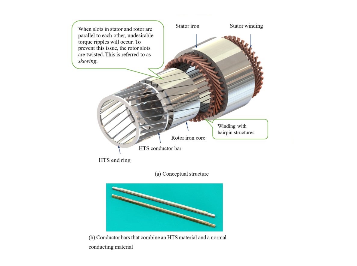
Illustration 17-3 shows an example of how the above structure is implemented. Illustration 17-4 shows an assembly of the conductor bars and end rings. For a basic experiment to check its principle, this motor has simple end rings in place. If it is required to drive this motor even when the HTS is in a normal conducting state, the normal conducting bars will also require separate end rings made of a normal conductor.
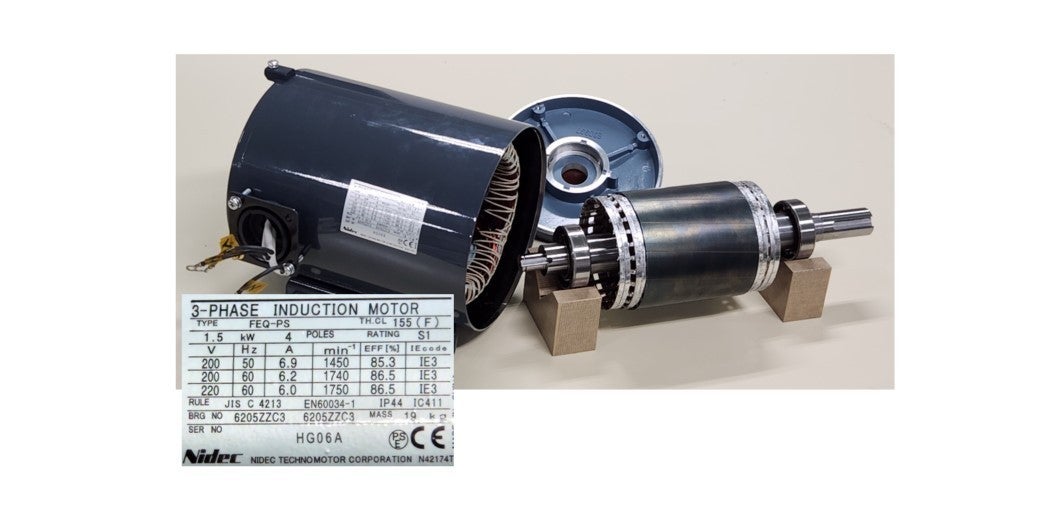
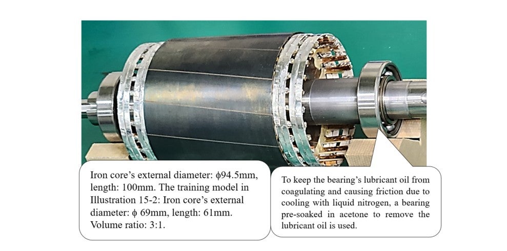
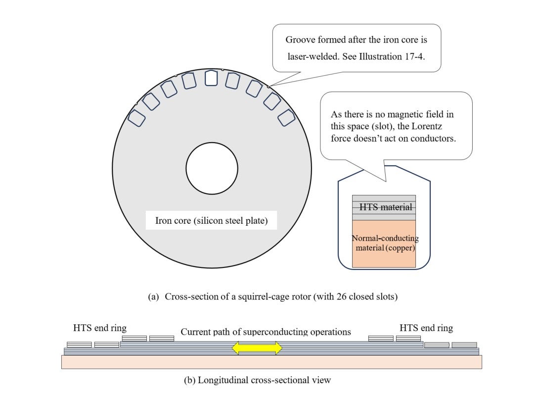
Illustration 17-5 shows a cross-sectional conceptual diagram of a rotor’s structure. (a) shows the cross-section of the rotor core. Its lamination is made of a 0.5mm-thick silicon steel plate, with bars installed in 26 closed slots. The lamination is laser-welded and laminated at 13 points. (b) is a conceptual diagram of an end ring’s welding installation.
Feature comparison: Induction machine vs. synchronous machine
(Synchronous-asynchronous availability)
The above is information regarding the motor’s structure. This section describes what kind of motor characteristics can be realized based on the relationship between the above structure and superconductivity.
First, let’s assume direct current is used in superconducting phenomena. In the rotor structure shown in
Illustration 17-5
, we assume that the electric current flowing into individual conductors is constant over time. Though the current’s direction and magnitude may differ for each conductor, we assume the current at
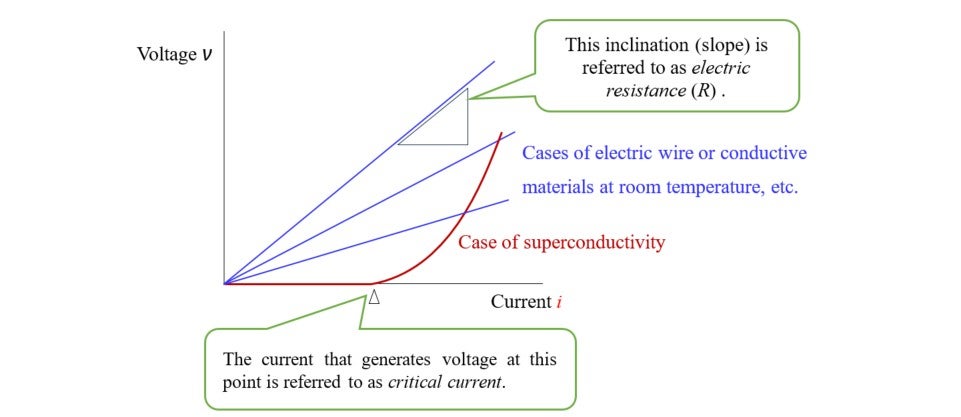
each position is at or below the critical current level. What is critical current? The voltage-current relationship shown in
Illustration 17-6
explains this. At or below the critical current, voltage does not appear in the conductor. In such a case, the rotor generates a magnetic field that does not change its direction like a permanent
magnet. So, the motor possesses the properties of a synchronous motor; that is
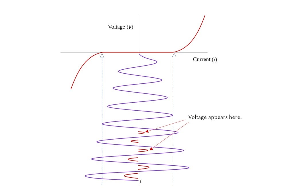
![]() =0. However, if the load is increased based on this operating method, the rotor will slow down slightly below the synchronous speed. Then, voltage is generated in the rotor’s winding based on
electromagnetic induction, and the current becomes a low frequency alternating current, exceeding the critical current as shown in
Illustration 17-7
. This state is similar to large current flowing in normal conducting materials, but the current flowing to the conductor bar is not direct current but alternating current that changes slowly at
approximately 1Hz. This state is similar to the condition I explained in the 15
th
lecture of this series, where the induction motor’s secondary resistance is low.
=0. However, if the load is increased based on this operating method, the rotor will slow down slightly below the synchronous speed. Then, voltage is generated in the rotor’s winding based on
electromagnetic induction, and the current becomes a low frequency alternating current, exceeding the critical current as shown in
Illustration 17-7
. This state is similar to large current flowing in normal conducting materials, but the current flowing to the conductor bar is not direct current but alternating current that changes slowly at
approximately 1Hz. This state is similar to the condition I explained in the 15
th
lecture of this series, where the induction motor’s secondary resistance is low.
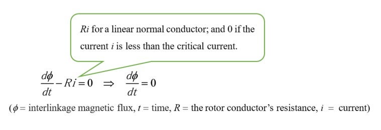
If the current i flowing through the HTS squirrel-cage winding is less than the critical current, then R becomes 0 and the result will be
 =constant, time-unchanging interlinkage magnetic flux. In other words, the magnetic flux will be captured. The rotor will behave as if it were a permanent magnet, and the motor will become a
synchronous machine.
=constant, time-unchanging interlinkage magnetic flux. In other words, the magnetic flux will be captured. The rotor will behave as if it were a permanent magnet, and the motor will become a
synchronous machine.
The above state means a smooth transition from a synchronous operation to an asynchronous one. This transition cannot take place with a synchronous machine that uses strong permanent magnets. This phenomenon is called synchronous pull-out, where the rotor stops rotating all of sudden. What happens if a weak permanent magnet is used? The answer to it is the hysteresis motor, which continues to rotate smoothly even after synchronous pull-out. This is the phenomenon described as synchronous-asynchronous availability in Illustration 17-8 . Depending on load, an HTS induction motor becomes either a synchronous machine or an asynchronous machine automatically – similar to a hysteresis synchronous motor. However, a difference is that an HTS induction motor can generate a significantly larger synchronous pull-out torque compared to a hysteresis motor.
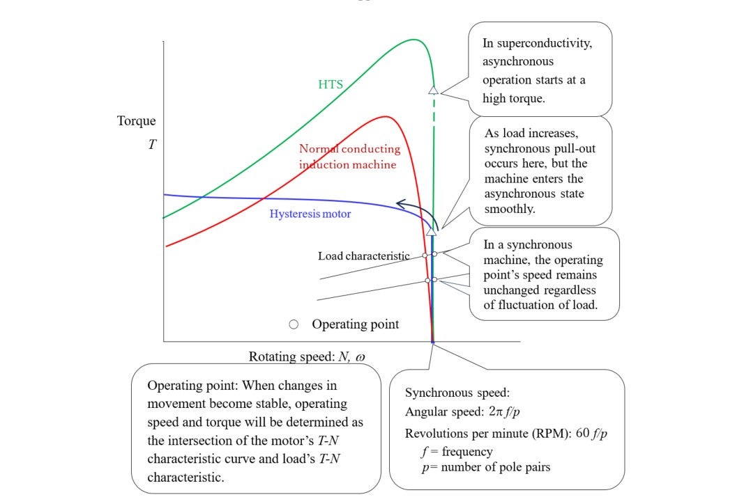
When an HTS induction motor starts, it goes through asynchronous (slipping) rotation and then converges to synchronization. This asynchronous operation can be realized even in the steady state, i.e, this implies compatibility with synchronism. The results of a loaded test shows that a maximum synchronous output of 20 kW was achieved even in a case with the stator iron core of an industrial motor with a rated output of 3.7 kW. When an even larger load was applied, an output more than twice the maximum synchronous output (41.3 kW; rotation speed: 1760 rpm, slip = 0.022 at 60 Hz) was achieved [5] . That shows an output more than 10 times the original output was achieved easily. During its normal rotation, the motor rotates in a high-efficiency synchronous mode. On the other hand, when applied with an overload, the motor autonomously shifts to asynchronous mode, continuing its rotation albeit generating loss. Thus, the HTS induction motor can possess overload capability.
The prototype shown in Illustration 17-4 is a motor in which the squirrel-cage rotor winding of the original induction motor with a rated output of 1.5 kW was fabricated using HTSs. It demonstrated an output of 4.5kW, three times the rating, in an initial experiment. Many textbooks explain the torque of a motor with the Lorentz force. However, only a few motors, such as coreless DC motors, actually use the Lorentz force. On an economic basis, 99% or more of motors rotate with the non-Lorentz force. It was Teare’s non-linear theory that explained the non-Lorentz force, as I discussed in lecture 11. This theory systematically explains the relation between the torque and iron loss due to magnetic hysteresis. Furthermore, in lecture 13, I provided a detailed explanation on the relation along with the inductor-based torque principle. It is intriguing that not only does superconductivity exhibit similar characteristics in terms of torque generation, but it also possesses even more significant functions.
Stable acceleration
The HTS is characterized by extremely low loss, which achieves high efficiency and torque characteristics of motors. On the other hand, low resistance means that the motor cannot be controlled, raising concerns that the motor can easily start vibrating unstably upon a sudden acceleration and deceleration. However, an HTS induction motor can maintain stable rotation, due to its non-linear resistance shown in Illustration 17-6 . A case of 20 kW-class motor is shown in reference [6] . It describes that, even with a load 1.5 times the rated output, the motor reached steady-state speed in acceleration time of 0.4s without vibrations. For the prototype shown in Illustration 17-3 , we used an inverter * , not a commercial 60Hz power source, to conduct an experiment at 38Hz. As a result, we confirmed a 4.5kW output, which is three times the rated output of 1.5kW.
There is an electric power regeneration mechanism deeply related to the improvement of energy efficiency. When an electric vehicle goes down a slope, gravitational potential energy is converted into electricity, and the battery is charged. Reference [7] describes the excellent features of an HTS induction motor in this technology.
* Inverter: an electronic circuit that uses transistors, FETs, etc. to convert direct current into three-phase alternating currents of required voltage and frequency.
Future prospects
Kenjo:
have so far described mysteries surrounding motors in 17 lectures of this series. When discussing motors, the three main pillars are important:
1) the mechanical structure itself,
2) the electric and electronic circuits to drive the motor, and
3) control items such as rotating angle, speed, and torque.
In this series, I focused mainly on the structure and the physical characteristics of the materials used. Professor Nakamura, you are implementing researches into using the HTS materials in the
structure of induction motors, a typical type of motor that does not use permanent magnets. Will you comment on future prospects?
Nakamura: Approximately half of electricity generated around the world is used for motors. As stated in this series, while many types and applications of motors exist, industrial squirrel-cage motors account for a significant portion of the electricity consumption. This is one of the reasons that I chose the application of superconductivity to this kind of motor for my research theme. The range of the outcomes of this research is wide, in my opinion.
Kenjo: Can your technology be applied to rotate airplane propellers? I apologize for talking about myself, but when Nidec Motor Engineering Research Laboratory was established in 2005, one of the themes was the creation of a small, high-power motor. In order to have a clear goal, we chose the F5B racing glider. The key was to design a motor that could lift the aircraft 150 meters above the ground in two seconds. We were successful, and a young pilot from Italy won the F5B 2010 World Championship, using our motor. Based on the data from that time I recently tried to design a motor for a human-carrying eVTOL, but found that heat in the stator windings can be extremely high as long as normal copper wire is used. Professor Nakamura, can we use your HTS technology to resolve this issue?
Nakamura: In the area of transportation, the construction of the linear maglev Chuo Shinkansen is underway, but it seems to take several more years before its realization. Other possible transportation equipment include cars, ships, and airplanes. Particularly active development of HTS motors aimed for electric aircraft is ongoing world widely. However, from my perspective as a rotating machinery expert, at least on a published basis, a structure that guarantees performance close to practical use has not yet been made clear. In particular, there seems to be not many research results that clarify the loaded characteristics as experimental data, so it is essential to first build a solid track record as a HTS rotating machine. Automotive drive motors typically have a maximum output of over 100 kW and an average output in several tens of kW range. When operating them while cooling with a separate refrigeration system, it becomes difficult to find advantages in terms of efficiency and cost. However, hydrogen engine vehicles equipped with liquid hydrogen tanks (the boiling point of liquid hydrogen is -253°C) are being developed for racing purposes, so if we can utilize such cold environments, we may be able to leverage the advantages of HTS motors. In fact, we at Kyoto University, in collaboration with Torishima Pump Mfg. Co., Ltd., have successfully conducted pump combination tests on the liquid hydrogen pump. We are working on as part of the NEDO project, achieving a world maximum flow rate of 30.5 m3/h and a world highest pressure of 1.6 MPa for machines in the tens of kW range at a speed of 5,000 rpm, making practical application in sight.
Kenjo: My last question: What are the major challenges if we further advance and make the stator windings also utilize superconducting materials?
Nakamura: A motor in which not only the rotor's (field) winding but also the stator's three-phase windings for alternating currents are made of HTS materials is called a fully-superconducting motor, and this is considered the ultimate form of a high-efficiency superconducting rotating machine. However, even in no-load tests, there are few successful examples [8] , and regarding clear successful examples of loaded rotation tests or variable speed tests published, my group is currently the only one in the world, making it a rotating machine with generally high hurdles [9] . Furthermore, when the superconducting 3-phase stator windings are excited with a 3-phase voltage source, there is a risk of unbalanced currents and issues with alternating current losses; i.e. when an alternating electromagnetic field is applied to superconducting materials, losses occur due to a mechanism similar to the hysteresis loss. So, we must be cautious.
Kenjo: Thank you very much Professor Nakamura.
References, etc.:
- [1] Jungwook Sim, et al.; Test of an Induction Motor with HTS Wire at End ring and Bars, IEEE Transactions on Applied Superconductivity, vol. 13, no. 2, 2231–2234, 2003
-
[2]
Press release by Torishima Pump Mfg. Co., Ltd. on its superconductive liquid hydrogen pump; Torishima and Kyoto University Make Hydrogen History with World’s First High-Flow, High-Efficiency
Liquid Hydrogen Pump
(https://www.torishima.co.jp/common/uploads/sites/2/2024/03/20240314a-.pdf) - [3] Taketsune Nakamura, et al.; Development of 50-kW-Class High-Temperature Superconducting Induction/Synchronous Motor with Continuous Drive Characteristics from Room Temperature, IEEE Transactions on Applied Superconductivity, vol. 33, no. 5, 5200205, 2023
- [4] Hiroki Kitano, et al.; Controllability of HTS Induction/Synchronous Machine for Variable Speed Control, IEEE Transactions on Applied Superconductivity, vol. 33, no. 3, 5202505, 2013
- [5] Taketsune Nakamura, et al.; Experimental and analytical Study on Torque Density Maximization of High Temperature Superconducting Induction/Synchronous Motor, Proceedings of 2018 International Symposium on Power Electronics, Electrical Drives, Automation and Motion (SPEEDAM 2018), 1179-1184, 2018
- [6] Ken-ichi Ikeda; Basic Research on Nonlinear Current Transport and Rotational Characteristics of High Temperature Superconductor Induction/Synchronous Motors Toward the Establishment of Optimal Design and Drive Methods, Master's Thesis (Department of Electrical Engineering, Graduate School of Engineering, Kyoto University, Japan) (2018) (in Japanese)
- [7] T. Karashima, et al.; Experimental and Analytical Studies on Highly Efficient Regenerative Characteristics of a 20-kW Class HTS Induction/Synchronous Motor, IEEE Transactions on Applied Superconductivity, vol. 27, no. 4, 5202605, 2017
- [8] K. S. Haran, et al.; High power density superconducting rotating machines—development status and technology roadmap, Superconductor Science and Technology, vol. 30, 123002, 2017
- [9] T. Nakamura, et al.; Quantitative characterization of nonlinear impedance and load characteristic of 50 kW class fully superconducting induction/synchronous motor, Physica C, vol. 578, 1353662, 2020
***** Column: The Lives of Two Geniuses - Bardeen and Teare
Not a few readers know that John Bardeen won the Nobel Prize in Physics twice, for the invention of the BCS theory and the transistor.
In the 11 th article of this series, I wrote about the mysteries of the non-Lorenz force, and discussed Benjamin Teare’s hysteresis motor-based torque theory. I also demonstrated that by expanding his idea, one can explain the inductor motor, which is a typical case that uses the non-Lorentz force.
Bardeen and Teare were classmates at the University of Wisconsin. In 1928, when progressing from undergraduate to masters’ studies Teare changed his major from physics to electrical engineering, while Bardeen changed from electrical engineering to physics. Bardeen was curious to figure out the essence of matters, whereas Teare had discerning and mathematical skills to quickly make practical results. Teare was scouted by General Electric to join them. Bardeen and Teare seem to have worked at Naval Ordinance Lab in 1941, but they are in different departments.