Quest For Motors' Hidden Abilities and New Potentials
Lecture 18: Magnetic Levitation (Maglev)
Do we humans dream about floating in the air? Let’s break away from the constraints of the universal gravitation, and levitate by using electromagnetic force. It would be interesting to image if we can control such movements.
A new type of magnetic levitation
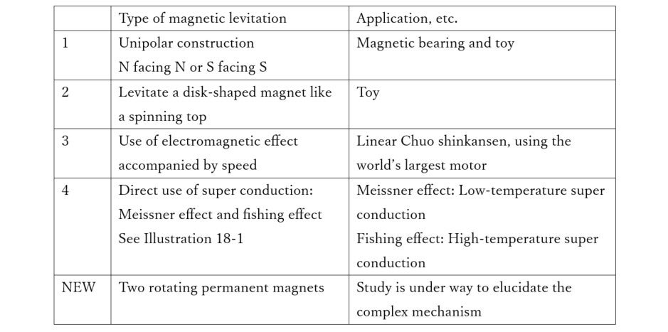
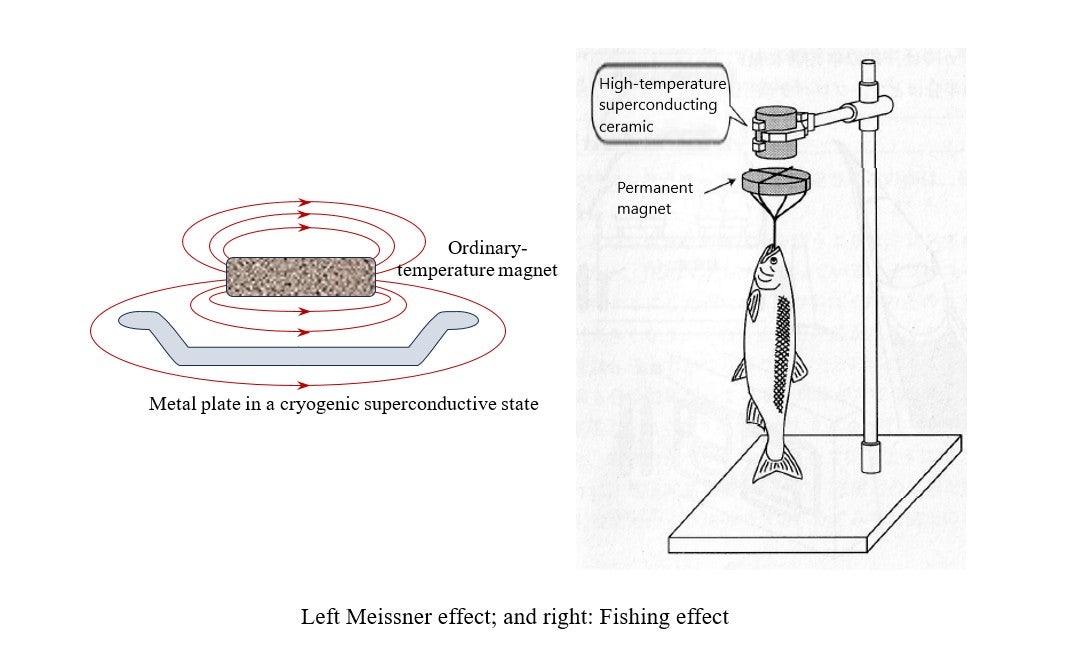
It was 27 years ago that I wrote on magnetic levitation for the final chapter of my Japanese book “ Zukai Wakaru Denki to Denshi (Electricity and Electrons) ” (Blue Backs Series B249, Kodansha Ltd.). What is new now in this science area? Sections 1-4 of Table 18-1 below are a summary of the main magnetic levitation methods that I explained in this book. The principles and explanations of these methods can be explained with no particular problem. 1) and 2) are applied to toys available online and via other means. The method of using a magnet to levitate another magnet is a technology adopted widely, ranging from toys to maglev trains, leading people to believe that there was little left for further research. 3) is a basic science technology for the planned linear Shinkansen train) whose completion is being delayed. 4) is directly related to superconductivity, the topic I selected for my previous lecture, which focusses on Professor Nakamura of Kyoto University. The “New” section is a matter related to the topic in this lecture.
Floating a spherical permanent magnet
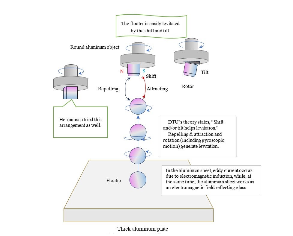
In 2021, Hamdi Ucar of Göksal Aeronautics, in Istanbul, Turkey reported a new type of magnetic levitation [1] , capturing people’s attention. This new levitation is caused by a piece of a fast-rotating permanent magnet, about which others, including Hermansen of the Technical University of Denmark (DTU) in Copenhagen announced a detailed commentary [2] . Based on Ucar’s and other’s viewpoints, physical interpretation and analysis, Hermansen and others made a new proposal, discussing the gap between the rotating axis and the magnetic-pole axis by using a couple of cube-shaped two-pole permanent magnet (a “rotor” and a “floater”). First, Hermansen used two cube-shaped neodymium magnets, to rotate one of them with a drill-like tool, and levitate the other magnet. The magnet seems to have to rotate at its appropriate speed. Hermansen and others discussed levitation in the range of 200-400 Hz (12,000 - 24,000rpm). For this experiment, in addition to these two magnets, we need a drill and a thick aluminum plate. Another document [3] describes that Hermansen used a spherical magnet as a rotor, and extensively researched the sizes of the floater and the rotor, and the relations with the floater’s movement.
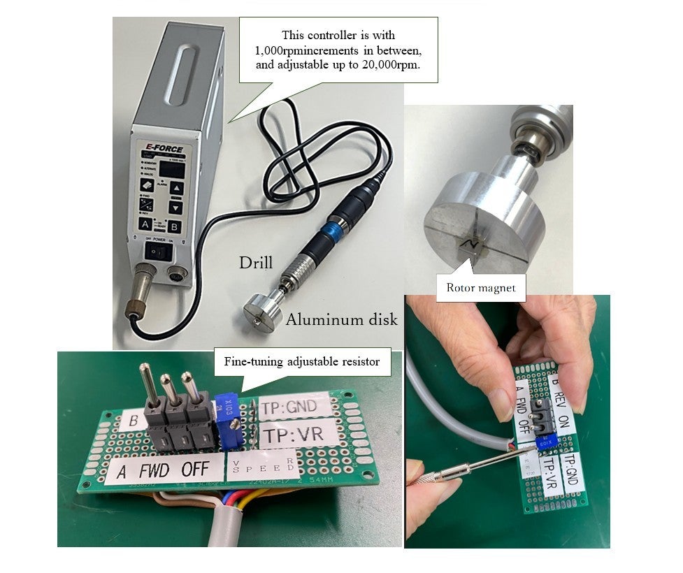
Most probably, university and corporate laboratories around the world are performing additional experiments on this new type of magnetic levitation. After reviewing Ucar’s and Hermansen’s papers, my colleagues and I drew a mechanism of the type of levitation as shown in Illustration 18-2 . Illustration 18-3 shows the equipment we prepared for experiments to examine the levitation. In this experiment, a metal-polishing hand tool (drill) rotates an aluminum disk in place of a grinding stone, and a rotor (rotating magnet) is attached to the disk. In Hermansen’s case, he first seemed to perform levitation by placing the rotor in such a way as shown in Illustration18-2. Ucar’s report, showing a number of arrangements for levitation, suggests how profound magnetic levitation is.
We were able to make a spherical floater placed on an aluminum table after some try-and- error. Our experiment procedure is:
- 1) First, place an aluminum table horizontally on a laboratory table (desk).
- 2) Put a floater on the aluminum table.
- 3) Hold the drill and bring the tip of the rotor close to about 7 cm above the floater.
- 4) Then turn on the switch to start the drill.
- 5) Next, there are two options. One is to accelerate the drill from low to higher speed gradually. The other option: After adjusting the drill speed around 5000 rpm or so, bring down the drill slowly to the floater.
- 6) Then, the floater starts to rotate, and, as the round object rotates faster, the floater starts to levitate.
Illustration 18-4 shows the floater levitating at approximately 5,500rpm as its rotating speed increased gradually from 2,000rpm to 5,500rpm. After the floater starts to levitate, and after the drill is tilted, the floater’s location becomes stable on the drill’s rotating axis. It is interesting that the axis’ rotating speed is much lower than in Ucar’s case (105,000rpm).
When installing the rotor on the aluminum disk, make sure to shift it and/or give it a tilt; otherwise, the floater won’t levitate. In all things, the basics are important, and it is natural to value the accumulation of those fundamentals. However, for the magnetic levitation in this case, what does the eccentricity (shifting and tilting) mean as deviations from the basics? One can image various ideas as to what they mean, and I wonder if a kind of wave phenomenon is hidden here.
What high-speed rotation means
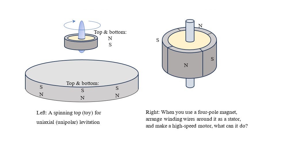
The second case shown in the various cases of magnetic levitation in Table 18‐1 is of a similar mechanism as the one on the left section of Illustration 18-5 . This is an easy-to-understand case where a ring-shaped magnet levitates over a magnetic plate. However, in a few minutes, the spinning top will lose speed and fall down the plate due to air viscosity. Then, can we create a mechanism where the spinning top keeps levitating by transforming the spinning top into a motor’s rotor like the image on the right of the illustration? That is exactly what a magnetic bearing does, and a number of laboratories and business bases must be trying to realize the mechanism. Aside from this topic, for the next lecture (the 19th lecture), I will present a mechanism where a device that rotates a rotor at a high speed to keep its attitude to the space, to make a jet airplane take off vertically and hover in the air. You will see that there is a phenomenon called precession movement to explain the relations between a fast-rotating spinning top and gravity or acceleration. High-speed rotation seems to possess mysterious effects.
References
- [1] H. Ucar, “Polarity free magnetic repulsion and magnetic bound state,” Symmetry 13, 442 (2021).
- [2] J. M. Hermansen et al ., “Magnetic levitation by rotation,” Phys. Rev. Appl. 20, 044036
- [3] J. M. Hermansen, “How Rotation Drives Magnetic Levitation,” October 13, 2023• Physics 16, 177