Quest For Motors' Hidden Abilities and New Potentials
Lecture 19:Avionic Motors for Aerospace Applications
In the previous lecture (Lecture No. 18), we discussed magnetic levitation. While that was related to magnetism, aviation and space technology can also be seen as a broader interpretation of levitation. This seems to be a wide-ranging and profound area of high-tech avionic motors. The term “avionics” started to be used in the early 1960s, when the transistor replaced the vacuum tube. Let’s consider it as electronics for the aerospace field.
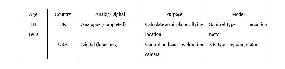
This time, I will discuss the design of two cutting-edge control motors in the aerospace field from the year 1963/64, and I intend to conclude with the theme of modern technology 60 years later in the next final episode. The first design is for the VTOL Harrier jet, created by the Great Britain’s symbolic Hawker Siddeley Group, and the second one is for the US lunar probe. This article is written in memory of Mr. Colin McDermott, who designed the former, and Mr. Katsumi Egawa, the designer of the latter. The term “VTOL” stands for “Vertical Take-Off and Landing (Aircraft).”
I often think about the types and applications of motors. At this time, whether they use a permanent magnet or not is one important consideration. Neither of the motors discussed here uses a permanent magnet, but the reasons for this are different for each. The motor for the Harrier jet is an alternating-current (AC) positioning motor that plays a part in attitude control. Even in the early 1960s, AC-driven, induction motor-type positioning motors were used because it was difficult to make a precise, analog semiconductor-based direct-current (DC) amplifier circuit. As I discussed in the 14th and 15th lectures, the advantage of the induction machine is that it does not require mechanical commutators, an electronic inverter, or permanent magnets. In the case of lunar exploration motors, the use of permanent magnets was banned to avoid disturbing the magnetic field on the Moon’s surface. These two cases are both for positioning motors, though one is analog-controlled, while the other is digital. At that time, a major trend in civilian technology was the transition from vacuum-tube televisions to transistor ones. Since these two engineers were focused on the design of the motor itself, I regret forgetting to ask whether their motor controllers were still using vacuum tubes or had switched to transistors.
Two Engineers
Though they lived far apart geographically from each other, Messrs. McDermott and Egawa were engineers of the same generation. The career of Mr. McDermott, who was a violinist as well, is provided in my ninth lecture.
In Japan, Professor Yasushi Watanabe of Tohoku University was an important scholar. After World War II ended in 1945, he spent approximately 10 years promoting the national project of adopting the US’s transistor and control technologies. When he was giving lectures on automatic control in 1953, Egawa was among the audience, listening to professor’s words carefully. For graduation research, he chose a theme of how to make an oscilloscope display the magnetic field in an AC motor. After graduation he joined Sanyo Denki Co., Ltd, and was assigned to design a two-phase servomotor. This type of motor was the mainstream analog-control motor. However, soon, Egawa and his supervisor were astonished by an article published in a US-published technology magazine. It was about a type of numerically controlled machine tool and the variable reluctance stepping motor used in it. As I will explain below, this type of stepping motor originated in the UK, but American entrepreneurs were more focused on the industrial capabilities of Japan than those of Europe, as they tried to search for and train Japanese companies that would test-manufacture US-designed precision motors. When the president of Los Angeles-based IMC Magnetics came to Japan, Egawa provided him with technical interpretation service. He recognized Egawa’s gifted talent. This occasion led Egawa to visit the United States in 1963 to launch the designing of aircraft motors, which were known as synchro.
Let me talk a bit about my background in the field of electric motors. It began in 1960 when I attended Professor Fukushima's lecture as a junior to Mr. Egawa. Professor Fukushima was from Tokyo Imperial University and his lectures were fluent. In the first of his 15 classes, I felt magic in the geometric similarity law of the windings for transformer and motor. In his final class, the professor slowly started talking about hysteresis motor in the category of special motors. Then, the principle of the magnetic hysteresis creating the self-activated synchronous motor came into my mind, with a pleasant rolling sound. In 1964 at TEAC (a high-end tape recorder manufacturer) when I was close to establishing the method to determine the number of winding turns and wire size for a two-speed hysteresis motor, my focus shifted toward physical matters such as the optimization of coercivity of rotor’s hysteresis material in relation to the number of magnetic poles in the stator winding. The following year, after submitting the results of my analytical calculation and experiments described in my unsophisticated English, I received responses from an Indian government agency and Mr. McDermott of Scotland’s Ferranti Limited. Then I knew that hysteresis motor was a precision motor important not only for audio equipment, but also for controlling the attitude of airplanes and intercontinental ballistic missiles. This occasion led me to start exchanging with the motor engineers of British companies, universities, and technical editors of Oxford University Press.
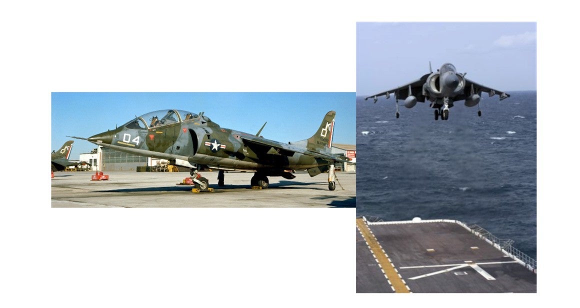
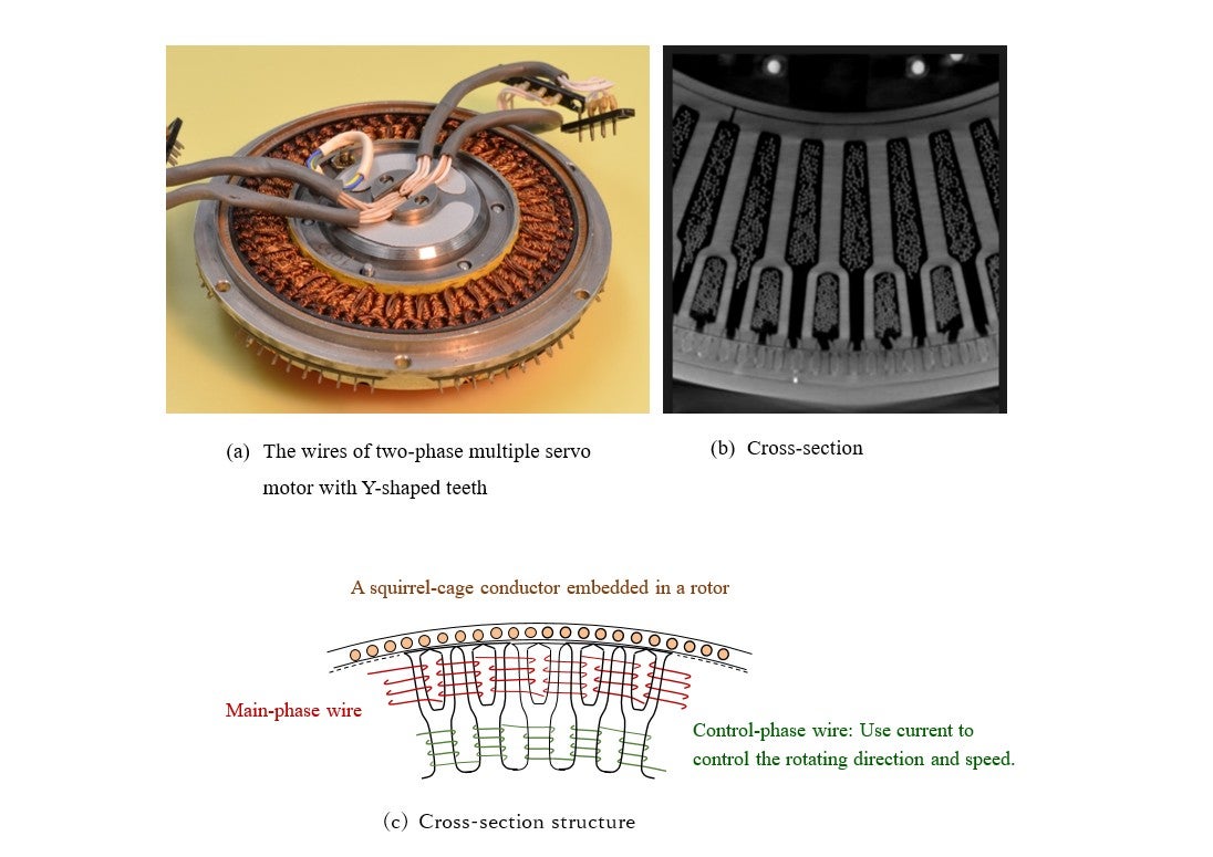
Photos 19-1 shows the VTOL Harrier Jet, a fighter plane first deployed around 1964, and capable of vertical takeoff using its jet engines. The squirrel-cage induction motor, shown in Illustration 19-2, is used to control the airplane’s attitude and position. Mr. McDermott, who once tried to become a Royal Air Force pilot, studied electrical engineering at Manchester University and was offered a position as research assistant at the University of Bristol in 1953. After conducting research on the variable speed induction motor, he joined Ferranti in 1957 to be involved in the development of this servomotor. This induction machine’s characteristics include Y-shaped teeth; high-density winding; and 400Hz, two-phase current-based driving and control. The only two cases of using Y-shaped iron cores in civilian motors that the author knows about are both for ceiling fans. The first case involves an induction machine based on this system, which uses a 60Hz two-phase current for North American households. This is based on the transfer of the VTOL Harrier jet’s technology to the United States under a UK-US agreement in the late 1970s (though the US had successfully developed an inertial navigation system, replacing the gyroscope with laser and relativity principles). It seems that a military engineer who participated in this project came up with the idea, after retirement, of converting this motor into a 60Hz one to produce electric fans using inexpensive materials. It was the motor company group in Taichung, Taiwan, that took this information both intelligently and seriously. The group designed and manufactured products not as a single company but jointly. Those products were low-speed ceiling fans that take advantage of the effects of air-conditioners installed in North American households. This is a good example of a military technology converted to satisfy private-sector demand. The other case involves the use of permanent magnets to improve the brushless motor’s electricity efficiency for Indian household applications.
From analog to digital control
The United States was preparing basic aerospace technology since the 1950s. In May 1961, the President Kennedy announced the Apollo Project, declaring that the US would send humans to the Moon before 1970. Prior to the announcement on the manned space mission, the Lunar Surveyor Program was launched to probe the surface of the Moon. As the reputation about the Japanese engineer spread in Los Angeles, a difficult task was brought to him from the Jet Propulsion Laboratory: To create, in a short time, an observational-equipment motor that would function under harsh conditions such as those where tremendous shocks are generated during a spacecraft’s vertical lift, and in space where temperatures fluctuate significantly.
The two motors discussed here were manufactured as cutting-edge aerospace equipment in the UK and the USA, respectively during the 1960s. Both are related to the two-phase, aircraft servomotor. The two-phase motor, a type of the squirrel-cage induction motor I discussed in my 14th lecture, is an AC (alternating-current) motor. Egawa used an iron core of the stator of an AC motor with a small number of slots, to develop a stepping motor that would digitally drive the lunar mission equipment’s mirror. Analogue technology could never use Earth-transmitted electrical waves to operate a motor. This fundamental structure as a motor was invented to be installed into British warships.
McDermott’s two-phase servomotor had a complex structure, which was the ultimate form of the squirrel-cage induction motor with an analog-like drive known as the rotating magnetic field. The stepping motor, on the other hand, uses a digital electronic circuit. Since bringing any permanent magnet to the Moon’s surface was strictly prohibited in the Lunar Surveyor Program, a variable reluctance-type (variable magnetic flux-type) stepping motor was designed. In 1966, when the first unmanned Surveyor was launched and landed on the Moon’s surface, the space craft transmitted images from there. I believe that in this spacecraft as well, the self-sustaining inertial navigation method was used to calculate the rocket’s location in the solar system and its attitude, but the method may have used a different principle from the one used in the Harrier jet.
As I explained in Illustration 19-5, the stepping motor to rotate the lunar mission equipment’s mirror was operated using Earth-transmitted electric waves, which had to be digital pulse signals. Mr. Egawa created a VR-type stepping motor out of a two-phase aircraft servomotor. Let’s see the cross-section of the stepping motor’s stator and rotor. This illustration shows current flowing in the red wire, with the teeth of the stator’s iron core and that of the rotor in alignment. When the current is switched over to the green wire, a 15°step is made clockwise; whereas, when the current is switched over to the purple wire, a 15° step is made counterclockwise.
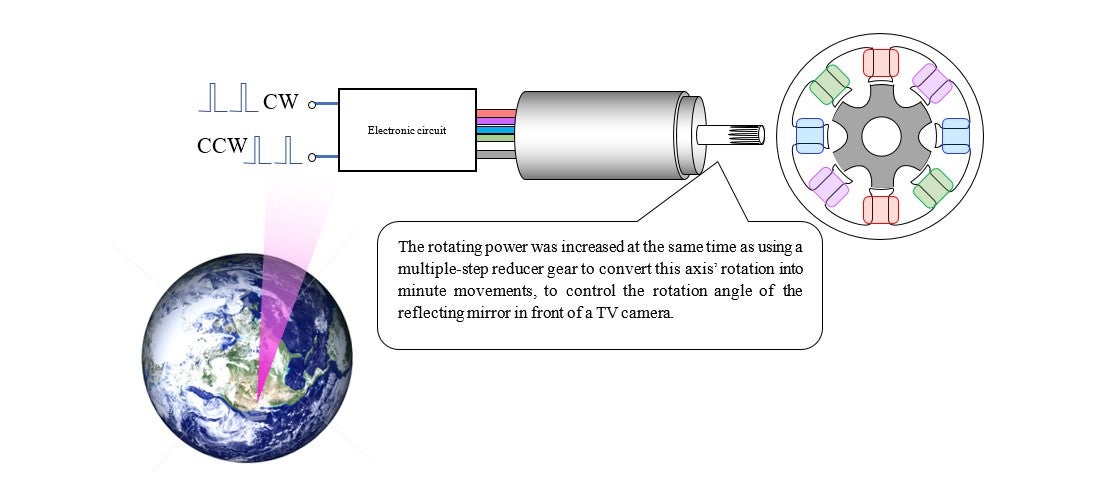
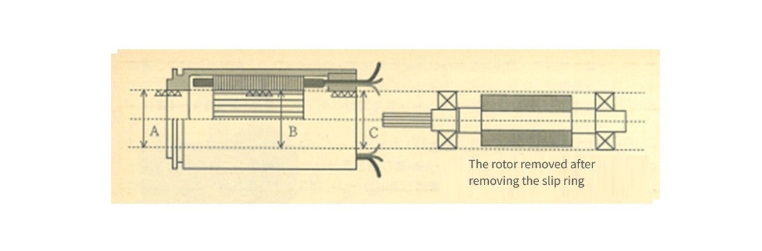
A small number of components and a simple structure are required to make space devices reliable (See Illustration 19⁻6). During the analog-to-digital transition in motor controls, Mr. Egawa used a through-bore method to accurately secure an air gap (the spatial distance between the stator and the rotor) accurately. This is how the permanent-magnet-free stepping motor was born.
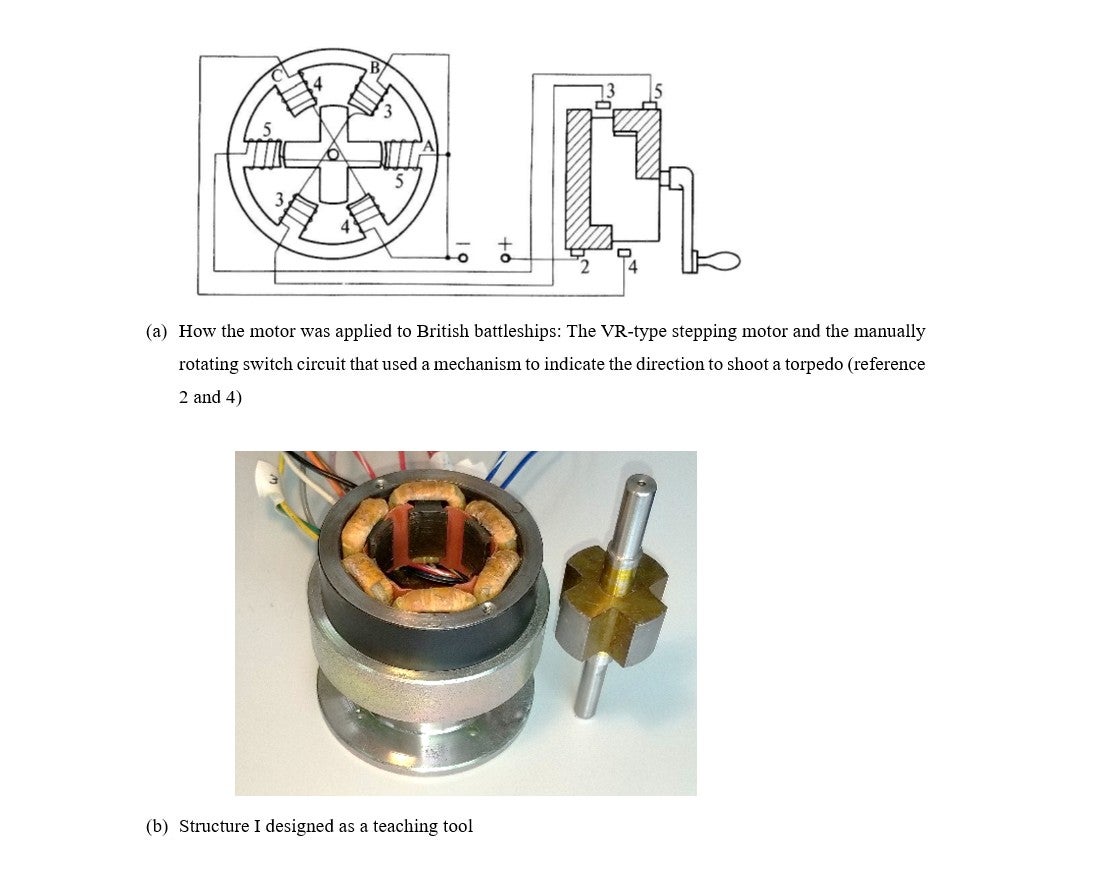
Illustration 7(a) depicts the principle of this stepping motor installed in UK battleships. Part (b) shows the motor that I designed as a technical teaching tool in the 1970s. When I showed Mr. Egawa this device, he told me that he had seen something very similar at a junk shop in Tokyo’s Akihabara District after World War II. This could be because the Japanese Imperial Navy introduced this technology from the UK. I described how Mr. Egawa developed his motor in detail in my Japanese book Motor wo Tsukuru (Making Motors, Blue Backs Series by Kodansha Ltd.). Reference [1] refers to the use of permanent-magnet-type motors in the Voyager Program.
References
- [1]T.Kenjo and A.Sugawara: Stepping motors and their microprocessor controls, 2nd: edition, Chapter 8, Oxford University Press
Inertial navigation equipment
This equipment measures the three-axis direction acceleration of a three-dimensional space, and using calculation algorithms, determines the position and attitude of an airplane, a submarine, etc. (Each device uses three motors of two different types.) One of them is a motor that retains its reference axis based on the spinning-top principle. The motor maintains its platform with its three (axes of) servomotors. The inertial navigation control originated in the German military’s V2 rocket used near the end of World War II. When Germany surrendered in the war, the Allied Forces quickly confiscated the rocket’s technology site. The MIT became combined in the US, making significant progress as part of the preparations for the Apollo Project.
Illustration 19-3(a) is a mechanism known as gyroscope, whose rotor acts like a spinning top that rotates at a certain speed. The larger the product of moment of inertia and rotational speed, the bigger the force maintaining its orientation. When rotating a spinning top on the ground or a table, one can see that the spinning top rotates vertically at first, and starts to tilt and wobble as it loses speed. This phenomenon is due to the Earth’s gravity. By thinking the other way around, one can calculate gravity based on the spinning top’s minute movements. Many readers probably know that Albert Einstein figured out the gravity-acceleration equivalence when he constructed the general theory of relativity. Installing this device into an airplane reveals the following matters:
A fast-rotating small hysteresis motor is appropriate as a spinning-top motor, and I described it in detail in my 15th lecture. In the rotation that the gyroscope detects, the angular rate means rotation in the outer space (inertial space). The gyroscope is called an inertial sensor.
In 1971, during his trip to the US to investigate the technological trends on motors in aviation instruments, Mr. Egawa witnessed a Boeing 747 jumbo jet performing a touch and go. It was also the 747 that introduced the inertial navigation system, developed as a defense aerospace device, into civilian aircraft. It may have also been the 747 that marked the beginning of the disappearance of electromechanical sensor displays from cockpits.