Quest For Motors' Hidden Abilities and New Potentials
Lecture 20:Towards eVTOL
Last time, I introduced the technical term avionics and briefly discussed motor design and control in this field. One example was the inertial navigation system developed for the VTOL Harrier. Since this field began in 1960, 65 years have now passed. In this final lecture, while looking back at the evolution of avionic motors over the decade of 2005, I will also touch on eVTOL, one of today's cutting-edge technologies.
Nidec motor that soared in the sky over Kyiv
Let's start with the avionics world competition held in Kyiv in 2008. This is the F5B World Championship, known as the Olympics of radio-controlled drones. Normally, early autumn weather in Ukraine is calm, but in mid-September 2008, the skies over Kyiv experienced unusual conditions. On the plains outside the city, 33 F5B competitors from 13 countries were flying their drones. In the 7°C fog, water condensed on the glasses of a Russian participant, while the hands of the Japanese competitors operating the controllers were numb. Nevertheless, drones equipped with a Japanese motor reached a height of 150 meters from the ground in just 2 seconds (equivalent to 270 km/h), outperforming the European drones powered by German motors.
The F5B aircrafts were manufactured in Ukraine, but no Ukrainian competitors participated. To withstand the centrifugal force when turning from propeller-driven to glider flight, the Japanese team's aircrafts used carbon fiber, crafted by Mr. Tsuyoshi Sakuraba (pictured later on the left in Photo 20-2). So, what about the Japanese-made motors? Who manufactured them? It was Nidec. There are numerous factories and offices that belong to Nidec. The Japanese motor was a handmade product from the Nidec Motor Engineering Research Laboratory (NMERL), with a diameter of 39mm and a weight of 385g. This exceeded the 7kW/kg of F1 engines at the time. Just before this world competition, we were conducting flight tests during Japan’s hot summer. The unexpectedly cold early autumn in Kyiv turned out to a favorable environment for the motor. Normally, the competition runs over four days with eight rounds, but that year it was frequently interrupted and ended after three rounds.
The servomotor used for the VTOL Harrier's attitude control was not unrelated to our avionic motors. In 1976, when I was shown this motor by Mr. McDermott at Ferranti in Edinburgh, I said to him, “'Surely its price is higher than an equal weight of silver, right?” He replied, “Not silver, but gold.” Even though the motor was made through precise machining of expensive materials and winding work by skillfully trained women, was it really that valuable? Or was it his self-assessment? At that moment, I felt a deep frustration. I realized that without knowledge of aerospace equipment, I could not yet be considered as an expert.
When NMERL was established in 2005, with the desire to overcome that long-standing frustration, I declared at the Kyoto headquarters auditorium that we would create the world's most powerful compact motor.
The shortcut to that goal was to develop a motor capable of winning the world electric airplane competition, known as the Olympics of this field. It was achieved in August 2010 with a team of roughly ten members.
Mr. Shigeru Sadotomo, who served as the de facto leader of this project, suspended his work as an ISO international auditor for over three years to dedicate himself fully to the planning of this avionic motor design. Through this effort, we learned what true teamwork means to achieve world-class motor performance. The work encompassed many domains including procurement of materials and parts, motor design, handling of permanent magnets, assembly of measurement instruments, design and installation of the wind tunnel, flight recorders, drive circuits, assembly, test piloting, communication with cooperative pilots, logistical support during competitions, and coordination with external collaborators.
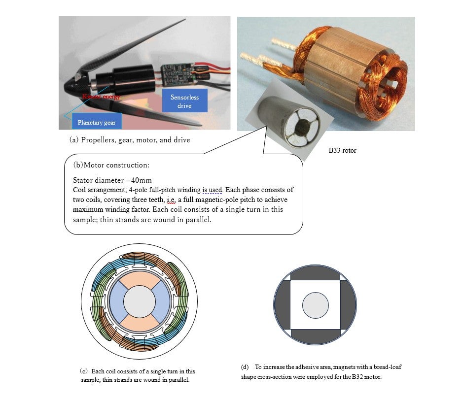
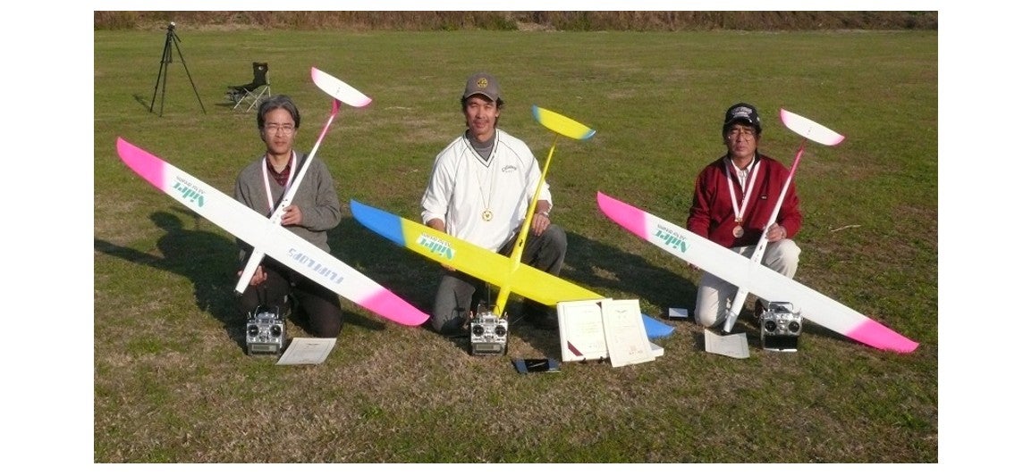
Then, qualified personnel began to appear to assist us in each of these areas. As our staff grew and motor performance in the U.S. and Europe was rapidly improving, the team developed and shared a quiet determination to surpass them. Illustration 20-1 shows photos and cross-sectional structures of the motor around 2008. There were also failures, such as rotor damage due to mechanical vibrations during test runs, and, demagnetization caused by heat and armature reaction. The drive circuit also presented significant challenges. However, in the first three years, we achieved results with the cooperation of domestic F5B pilots. Illustration 20-2 is a commemorative photo of a domestic competition in 2007, where the three pilots using our motors took first, second, and third place. The champion, Ken’ichi Ueyama, was an iconic figure in the Kanto (Tokyo) region, and possessed a big international network.
The following year, our next challenge was the world championship in Ukraine. As mentioned earlier, at the 2008 World Championship in Kyiv, we encountered various unforeseen circumstances, including the weather, and our team placed an unsatisfactory 4th overall. Although this was the highest achievement ever for a Japanese team up to that point, the experience of this crushing defeat would be utilized at the competition in Muncie, Indiana, USA, two years later.
Then, capable personnel continued to join us. As the team became more robust, and as the American and European motor performance rapidly improved, they shared an unspoken passion to surpass them. As the saying goes, "failure is the stepping stone to success." If one aims to be at the top, failure is necessary. By understanding and analyzing failures as steps on the path towards success, talent is nurtured.
Outstanding skills in the German-speaking world
To digress slightly, there is a NIDEC slogan rooted in Masao Naruse's philosophy: "Integration of Science, Technology, and Skill." Naruse, a rising star at Tohoku Imperial University in the 1930s, was dispatched by the Government to study the craftsmanship of Germany and Switzerland. Later he embedded these principles when he was inaugurated as the principal of the Polytechnic University of Japan. The author was a member of the university’s faculty, while President Nagamori and Vice President Kobe were students. The importance of this trinity was vividly demonstrated in efforts related to the avionic motor.
In F5B competitions, there are both team and individual events. Examining the history of the world competitions held biennially shows that the winning teams have consistently come from Germany and Austria. In other words, the dominance of German-speaking pilots was evident.
After the end of World War II, Germany and Austria were no longer able to design and manufacture real aircraft. It is said that their passion turned towards model airplanes instead. (Actually, the same happened in Japan. At Tohoku University, where Naruse returned, the Allied forces banned aviation-related research in the Department of Aeronautical Engineering, which was reorganized into the Department of Precision Engineering.) The strength of German pilots is underpinned by their extensive practice. They start work early in the morning, finish by 3 p.m., and then devote their long summer afternoons entirely to flight training. It's not a hobby, but the pursuit of their life goal.
Nidec motors produced world champion
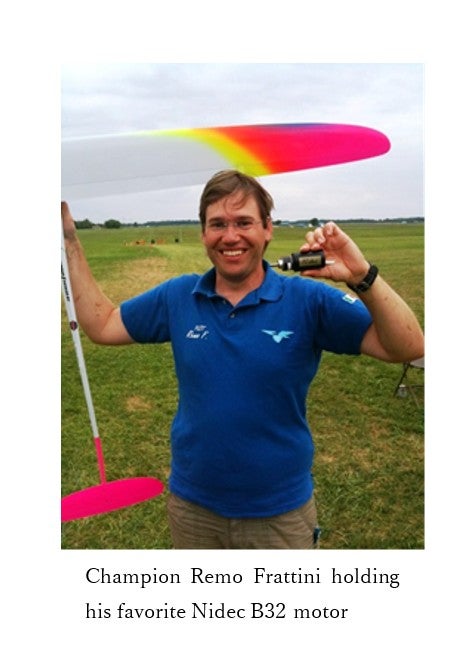
In 2006, Professor Nobufuji Kaji, an expert in mechanical engineering and thermodynamics at the Polytechnic University of Japan, joined NMERL. I stepped down to become honorary director, and he succeeded me as the director of the laboratory, supporting other projects behind the scenes. We realized that to create excellent motors and demonstrate their performance to the world, it was easier to achieve results in individual competitions rather than team competitions. For that purpose, it became clear that we needed to provide a NIDEC motor to a European pilot outside of Germany and Austria to help them polish their piloting skills. One of the valuable outcome of the Kiev competition under such circumstances was meeting a newcomer: Remo Frattini, born in Switzerland and residing in Italy. The story of how this young man until he became a champion was preserved as a long letter. Here, I record his feelings at the time he decided to use NIDEC motors.
So I just needed a good motor, controller and propeller combination. With all this, my chances would be real. So I decided to use the NIDEC B32 motor a Nidec engineer has kindly given me.

I knew from earlier tests that this is an extremely good motor. With the very strong Markus MX300 controller and an Avionik propeller I would have a very performing setup, I hoped. Flight tests then confirmed my assumption. My friend Ken Ueyama then helped me even more by lending me one of his B33 motors. Now I knew, I would have two very good setups with a small difference in runtime.
In this way, he became able to use the two models created by Nidec, but it was full of thrills; consideration of compatibility with the propellers was necessary.
Although I preferred the B32 motor, I later decided to use the B33 motor for the first flight of the. world championship, because total motor runtime was on the safer side. Although I didn't have a lot of time to practice before the championship, I was very confident and positive in attitude, because I knew that I probably had the best material.
Ken Ueyama helped me once more on the last day by giving me his propeller because he knew I .preferred the B32 motor. He also believed that the B32 was better in these circumstances. With his propeller I would have the right amount of runtime with the B32. And it all worked out! I did win the last two rounds. The motors performed perfectly. The last round was the deciding one. I knew I had to fly well if I wanted to win. I was nervous but I believed I could do it. I managed to fly smooth and well in the distance task. Only 10 more minutes for the duration task and the landing. These were probably the longest 10 minutes I ever experienced. Almost 10 minutes over, when entering for the landing, I knew no mistakes were allowed. I had to make a perfect landing. I was nervous. But everything worked out perfectly. The landing was on the spot. I was incredibly happy - I had won the world championship title!!
In such a way, Remo won the final race with his favorite B32 motor and experienced the moment of fulfilling his long-cherished dream. Here is a web article that reported this battle:
The F5B World Championship is held biennially and competed for between the world’s best pilots and teams. The 2010 contest-winning glider was flown by an Italian team pilot Remo Frattini, who ranked first among 37 contenders, and became the first BLDCM-equipped model glider to win the world title in the F5B class. In the 2010 contest, Frattini and three Japanese contestants used Nidec’s high-performance BLDCMs designed by Nidec Motor Engineering Research Laboratory. Nidec started providing Frattini with its BLDCMs two years ago in response to his personal request. Since then, Nidec has strived to enhance their BLDCMs for model aircrafts through stringent performance tests and countless joint trial flights with many world-class players. The 2010 World Championship title came as the result of a superb combination of Frattini’s extraordinary flying techniques and Nidec’s evolving BLDCM technology.
BLDCM stands for brushless DC motor
Design of compact, high-power motors and drive circuits
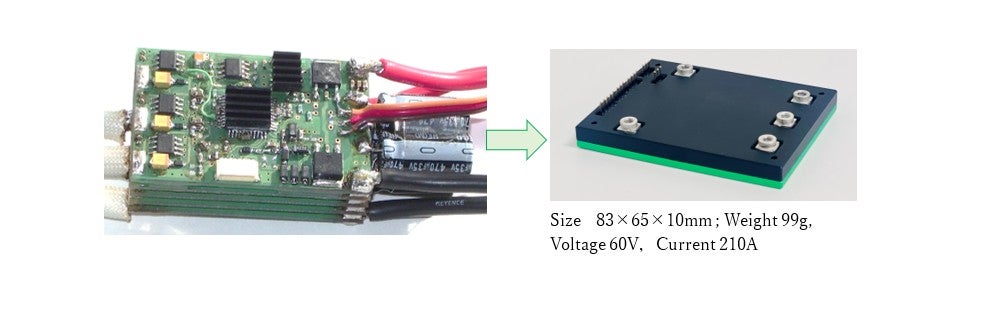
The creation of such small and powerful motors required theoretical calculations and technical skills in fabrication. However, when dealing with just a few motors or drive circuits, meticulous manual craftsmanship was also important. An expert has been trained to design drive circuits, understanding that not only high currents of up to 300A are being switched on/off by nearly 100 MOSFETs, but also logical signals to determine the switching timings are being transmitted in a tight space. See Illustration 20-3. He successfully arranged the semiconductor devices and carried out soldering work to build a compact drive circuit. (MOSFET = Metal-Oxide-Semiconductor Field-Effect Transistor)
One approach I often try is to understand motor characteristics through mathematical manipulation. However, it is still astonishing to see how an airplane's propeller can be controlled with just finger movement using a radio device.
At Nidec, after completing our work of improving motors for competition-type small drones, we applied the knowledge we had gained towards the design and control of motors for various devices, such as helicopter-type drones and robots.
Towards eVTOL: Importance of Science and Technology for Safety:
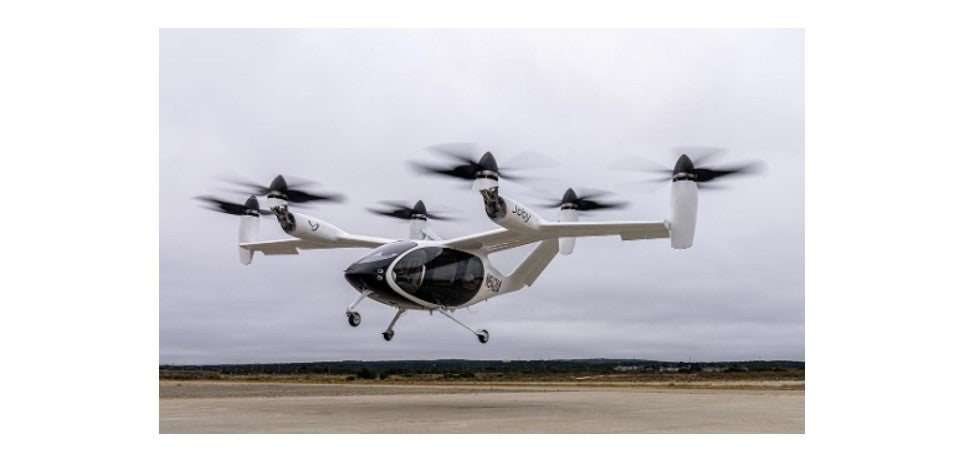
The contemporary topic of avionic motors is large drones—eVTOLs (electric vertical take-off and landing aircraft, Illustration 20-4)—such as those exhibited at the 2025 Osaka Expo. Our experience of developing a world champion small aircraft may serve as a guide into the field of electric aircraft that carries people. Even achieving the world’s No. 1 racing drones required ten team members, so the technical demands for eVTOLs capable of carrying people are on a completely different scale. Here, we focus on the science of the motor itself. By comparing the glider motors in Illustration 20-1 with those used in large drones, we will discuss the sophisticated techniques in motor design utilizing permanent magnets. One conclusion is that eVTOLs aim for motors with a high number of magnetic poles. The servomotors of the inertial navigation system in the VTOL Harrier were expertly designed, featuring many windings but no permanent magnets. It is intriguing to note a certain commonality between the two approaches.
One of the performance requirements for the motor is instantaneous power. Although the power supply voltage is limited to 25V, drawing a current as high as 300A can cause the voltage to drop below 20V due to internal resistance. At such a low voltage, the number of turns is at a minimum of 1, raising questions such as whether Y-connection is possible or if Δ-connection should be adopted. There were various challenges pushing the limits. During those years, through the collaboration of passionate motor designers and pilots, the output seems to have increased nearly tenfold. It is certain that without the 25V limitation, performance would have improved even further.
It is desirable for the motor structure to be as simple as possible, and a 12-slot 4-pole lap-winding was standard. The design requirements for compact high power involve a combination of high-speed rotation and reduction gears. The use of a planetary gear was reasonable in this context. For a motor with an outer diameter of about 40 mm, 4-pole scheme is suitable or standard for both the stator winding and the rotor’s magnet arrangement. (Note: This implies that the number of poles in the winding and that of the rotor are the same.) However, in applications such as flying cars, the propellers are driven directly without mechanical gearing for safety reasons. The rotation speed is relatively low, and the speed range is not very wide.
Consideration of armature reaction
In the 15th lecture on induction motors and the 19th lecture on variable-reluctance stepping motors, demagnetization caused by armature reaction was not an issue. However, this becomes a significant problem in a motor using a permanent magnet, as we clearly observed during the early stages of developing F5B-race motors. Let me explain this briefly.
In a permanent magnet motor, the fundamental relationship between torque T and current I is given by T = KE I. At first glance, it seems beneficial to increase the current I to obtain a higher torque T for propeller rotation.
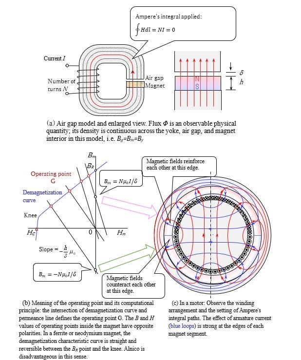
(a) A basic model in which a magnet piece is placed in the air gap of a C-type iron core and magnetized by the current in the winding. (b) Represents the mathematical meaning of magnetization, but this alone cannot fully explain the motor. (c) In motors, torque is maximized when the magnetic flux distribution by the magnet and the magnetic flux generated by the armature (stator) winding are orthogonal. However, the current passing through the armature (winding) can weaken the magnetic field at one edge of each magnet, potentially leading to demagnetization.
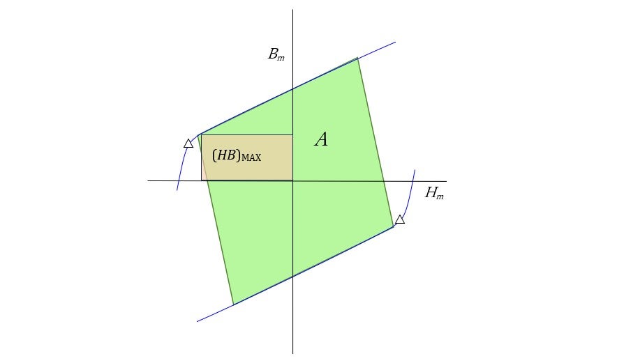
Naturally, the side effect of increasing the current is heat generation in the windings. More importantly, the strong magnetic field generated by the winding current can potentially damage the permanent magnets. Illustration 20-5 demonstrates the key points of this complex mechanism. Illustration (a) is a model applying basic Ampère's circuital law to the simplest case. This fundamental law was proposed by Ampère in Paris, seven months after Oersted's famous experiment in Copenhagen in 1820. However, the problem of demagnetization of permanent magnets was not addressed by this law until much later. The issue of demagnetization became a common topic among motor designers, particularly during the design and development of DC motors using Alnico magnets. Alnico has a high remanence BR, but a low coercivity HC, resulting in a small effective maximum energy product (BH)MAX.
Ferrite magnets, which have low remanence but high coercivity, are less prone to demagnetization. As shown in (b), the demagnetization characteristic curve is linear and reversible between the BR point and the knee in a Ferrite or neodymium magnet. As long as the operating point G remains on the right side of the knee, the B-H relationship is reversible. However, once it has shifted to the left of the knee, the magnetization state of the permanent magnet cannot recover. Alnico is disadvantageous in this sense.
The cause of the operating-point shift is explained in part (c). When the magnetic field at one edge of a segmented magnet is strengthened by the armature winding, the field at the other edge is weakened. This can make G enter the irreversible region; demagnetization. As a result, back-emf (electromotive force) coefficient KE decreases. Note that if the magnet is overheated, the knee shifts to the right, making it easier to demagnetize. Therefore, the armature current must be limited. In a motor structure, as shown in part (c), this demagnetization occurs first at one edge of each magnet segment.
In applications where a lightweight design but high torque is desired, a decrease in the torque constant could potentially lead to unexpected accidents. An effective measure to prevent this is to increase the number of magnetic poles in both the permanent magnets and windings as much as possible. For example, designs with 78 or 80 magnet poles are implemented. If the 4-pole structure shown in Illustration 20-1 is scaled up by a factor of 20, an 80-pole design is obtained. As a result, the number of winding slots becomes 12 × 20 = 240. The number of coils is also 240, and they must be manually wound in layers.
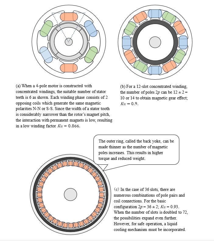
One of the main elements to maximize torque is the winding factor KW. It quantifies the utilization rate of the magnetic flux produced by the permanent magnet (or rotor’s winding and currents in the case of induction motor) . For a choice of 240 coils in a lap-winding, this factor reached its maximum, i.e. 1. An alternative and simpler approach is to use concentrated winding, where the number of slots can be 80 − 2 = 78 which yields a winding factor very close to 1. So why didn't we use concentrated windings for the F5B motor? In that case, it would employ a 6-slot stator as shown in Illustration 20-6(a). The winding factor of this design is 0.866. However, this design is often used for office-automation equipment, likely because it can generate sufficient torque even with low utilization of the permanent magnets.
Illustration 20-5(b) presents the operating point G and demagnetization of a magnetized permanent magnet. Here, 20-5(a) depicts a basic model in which magnet pieces are placed in the slots of a C-type core and magnetized by the current in the winding. Illustration 20-6(b) shows an example of concentrated winding in a 12-slot stator. In this configuration, the permanent magnets have either 12±2=10 or 14 poles, and in both cases, KW ≈ 0.9. In the 36-slot configuration of Illustration 20-6(c), KW = 0.93. If the number of slots is further increased to 72 or 78, resulting in 80 poles, KW further approaches 1. However, caution is needed regarding negative effects of a higher pole count. For example, an increase in driving frequency can lead to increased iron losses. Furthermore, various magnetic structures have been proposed such as inner rotor, outer rotor, axial-flux, and double-stator designs. However, in aircraft applications, simplicity of structure remains a crucial consideration.
Footnote***
Even for induction machines that do not use permanent magnets, the winding factor is an important indicator; however, discussing it requires considerable space, and is therefore omitted here.
Calculation of toque density
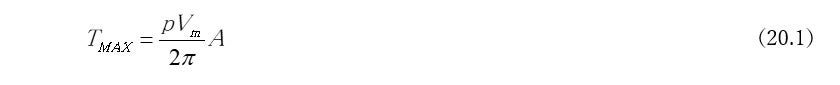
Let's discuss one of the principles for estimating torque per unit weight, focusing on the configuration of an 80-pole (p=40) motor. In the ideal case with many slots and closed slot-opening, the maximum allowable torque can be calculated from the diagram in Illustration 20-7 . If the area of the parallelogram is A, the theoretically maximum allowable torque is given by:
From a practical standpoint, let's consider how many times the maximum energy product A can be obtained. We introduce the magnet utilization parameter κ and define it as follows.

Now, let's assume:

And, given a magnet volume Vm , estimate the maximum allowable torque. Assume a cylindrical shape with a diameter of 400 mm, thickness of 6 mm, and height of 50 mm, then the magnet volume is:


Assuming the specific gravity of the magnet is 7.55, the total weight of all magnets is approximately 2.82 kg. How many times the magnets’ weight can be the total weight of the motor, including the cooling mechanism? This is the main issue. If we assume this ratio to be 10, the resulting torque density is

Including drive devices such as inverters, a torque density of 116 Nm/kg can be expected not to be 10 times, but 20 times that of the magnets.
Footnote***
Two coefficients serve as indicators of permanent magnets utilization: winding coefficient KW and magnet utilization parameter κ which is discussed here. KW is an indicator that has significance also for an induction machine, which does not use a permanent magnet, but κ is irrelevant to this motor. However, κ is regarded as the most important indicator for motors aiming to achieve compact, high-torque performance using rare-earth permanent magnets.
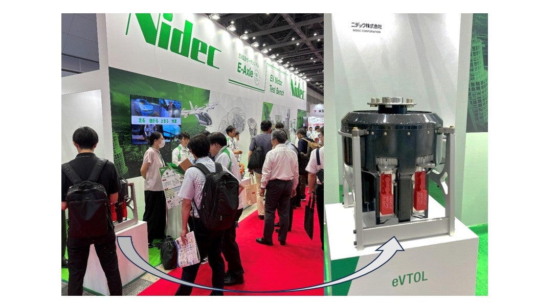
The photo in Illustration 20-8 shows a motor being developed for eVTOLs, as exhibited at the Techno Frontier Show in July 2025. Driven by such motors, an eVTOL lifts itself vertically using eight lifters. At a propeller rotation speed of approximately 130 rad/s, the required torque is 1.8 kNm, and the output is 234 kW. Since the previously mentioned 6.53 kNm is 3.63 times 1.8 kNm, there seems to be a sufficient margin. However, continuously operating at 5–6 kNm would generate much heat in the windings. Could superconductivity eliminate this Ohmic heating by replacing the copper wire with a special material? There is not yet reliable prospect for superconductors that carry alternating currents. This remains one of the conventional technical challenges. Winding
Another, much more fundamental issue is the second law of thermodynamics and the problem of increasing entropy. While this problem may be discussed at a cosmic scale, it also relates directly to the unacceptable global warming we are facing nowadays. Einstein once wrote that he became aware of the profoundness of thermodynamics while studying at the Polytechnic in Zurich. The second law, which symbolizes this branch of physics, concerns the increase of entropy. Entropy S is a physical quantity defined as the energy J divided by the temperature Q, i.e. S = J/Q. It is commonly interpreted as a measure of disorder. The second law states that all physical phenomena tend to increase S towards greater disorder. (For reference, the first law is the law of conservation of thermal energy.)
When I was 18, in a physics lecture taught by a senior professor, I learned that this law implies the eventual end of the universe. Even though this end might be tens of millions of years away, I felt a sense of melancholy. The following year, when I decided to major in electronic engineering, I was struck with excitement in the explanation of the photoelectric hypothesis by a young, newly appointed assistant professor. I was impressed by how Einstein discussed entropy using Boltzmann's statistical mechanics and how, through calculations, he deduced that light exhibits particle-like properties. This happened in March 1905. Two months later, he discussed the elucidation of Brownian motion. This work was important in confirming the existence of atoms; Einstein clarified that Brownian motion is caused by the irregular collisions of molecules in a thermally moving medium.
The paper he submitted a month later, in June, which is today known as “the special theory of relativity,” was titled On the Electrodynamics of Moving Bodies[1]. There is something mysterious hidden in this history. As he later revealed in a letter, Siemens' unipolar machine inspired Einstein to build this epoch-making theory[2]. If so, the moving body must have been the rotor of this machine as I discussed in Lecture 12. However, as one continues reading this paper, the moving body curiously becomes an electron, and Einstein derives that its mass increases with velocity. i.e. the Lorentz transformation.
In most commonly available books on relativity, his theory appears unrelated to entropy or the statistical theory of molecules and atoms. However, these ideas were not separable in the mind of the young Einstein. In my view, the science of motors is a garden blooming in the realm of special relativity. The key wonder lies in the short September paper[3], which starts with
The result of a recently published electrodynamic investigation in these annals by me leads to a very interesting conclusion, which shall be derived here.
This paper is sometimes referred to as “the paper on ![]() the world's shortest equation,” yet Einstein did not explicitly write this formula connected by equal sign (=). Prior to this, Larmor in Cambridge and Hasenöhrl in Vienna had independently presented
the world's shortest equation,” yet Einstein did not explicitly write this formula connected by equal sign (=). Prior to this, Larmor in Cambridge and Hasenöhrl in Vienna had independently presented ![]() , but it seems that Einstein was unaware of them. With relativity, the factor 4/3 disappears and the physical meaning of
, but it seems that Einstein was unaware of them. With relativity, the factor 4/3 disappears and the physical meaning of ![]() changes decisively.
changes decisively.
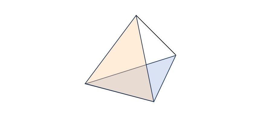
The photoelectric effect, Brownian motion, the theory of relativity, and the equivalence of mass and energy are represented on the four faces of a tetrahedron.
In 1915, Einstein published the theory of general relativity. How is the increase of entropy handled in that context? Sir Roger Penrose, who considers himself Einstein's successor, contributed a letter to Physical Review in 1965[4] and developed the grand theory known as Conformal Cyclic Cosmology. This theory provides a mechanism to cancel out the increase of entropy. Penrose discussed it in his Nobel Prize lecture in 2020[5]. I told this story in the work with Shigeru Sano[6].
In closing, I would like to express my gratitude to Jehan Piaget, a young Swiss engineer and intern at Nidec Research Center, who kindly discussed this final article with me.
References
- 1.A. Einstein: Zur Elektrodynamik der bewegter Körper, Annalen der Physik, 1905
- 2.S. Siemer: Einstein in München, Kultur & Technik 02/2005
- 3.A. Einstein: Ist die Trägheit eines Körpers von seinem Energieinhalt abhängig? Annalen der Physik, 1905
- 4.R. Penrose: Gravitational collapse and space-time singularities, Physical Review Letters, Vol.14, No.3, 18 January 1965
- 5.R. Penrose: Nobel Lecture,ps://www.bing.com/videos/search?q=penrose+nobel+lecture&go
- 6.T. Kenjo and S. Sano: Spacetime geometry of relativity, World Scientific Publishing Company, 2025
Quest For Motors' Hidden Abilities and New Potentials
- Lecture 1: Nikola Tesla and the Invention of the AC Motor
- Lecture 2: Steinmetz and the Hysteresis Motor
- Lecture 3: Einstein's Theory of Relativity and its Relation to Motors
- Lecture 4: Motors and the Flow of Energy in Electromagnetic Fields
- Lecture 5: Ultrasonic Motors—Mimicking the Movements of Human Hands
- Lecture 6: The Advance of Electronic Devices and Motor Technology
- Lecture 7: The Advance of Transistors and Motors
- Lecture 8: The Advances in Semiconductor Technology that Created the Field of Power Electronics
- Lecture 9: Compact Motors that Utilize Neodymium Magnets and Their Increase in Torque
- Lecture 10: Chuo Shinkansen (Bullet Train)—The World's Largest Motor
- Lecture 11: The mystery of non-Lorentz force
- Lecture 12: Special theory of relativity derived from Siemens’ unipolar machine
- Lecture 13: Induction Motor and Inductor Motor
- Lecture 14: Mysteries of the Induction Motor – Considerations based on a Transformer Model
- Lecture 15: The Case of the Three-phase Induction Motor
- Lecture 16: The Structures and Types of Synchronous Motors
- Lecture 17:The Superconductor Induction Motor
- Lecture 18:Magnetic Levitation (Maglev)
- Lecture 19:Avionic Motors for Aerospace Applications
- Lecture 20:Towards eVTOL