2-1-1. Reviewing the Principle of DC Motor Rotation
I think some of you might have understood the DC motor rotation principle in school by understanding the attractive and repulsive forces of magnets. You will have learnt more about motor rotation principles by using the law of BLI and Fleming's law (to be described later). To say "Fleming's law" may sound smarter than explaining "the N-pole or S-pole of a magnet......" and Fleming's law appears more academic as it can be used for calculating force generation.
But, wait a moment, please.
When you disassemble a DC motor, you will find the wire (coil) wound around a strip of iron. When the iron is nearby, the magnetic flux is concentrated in the iron portion, and almost no magnetic flux is present within the coil section (wire) (see Fig. 2.18 to be shown later). In this condition, it is not possible to explain the DC motor rotation principle using Fleming's law that states, "For a current-carrying wire in a magnetic field ........."
Nevertheless, school physics or electrical engineering textbooks cannot be wrong. So how should you think about this? To master any kind of technology, it is important for you to understand things concretely based on actual experience in addition to understanding them in your head.
To do this, we will study motor rotation principles and rotating speed in depth by using familiar subject matter found around yourself as leads and clues.
Firsthand Application of DC Motor Operation
If you have a motor used in a model, let's operate it.
- <1> Connect the motor to a 1.5-V dry battery, and rotate the motor.
The motor should start running and you should hear a soft sound. This is called no-load operation. - <2> If the battery connection is reversed, the motor rotation reverses.
- <3> If you load the motor by lightly pinching the motor shaft with your fingertips, you will feel the rotative force (torque) transmitted to them.
The running sound of the motor changes and the rotating speed may seem to decelerate. - <4> If you pinch the shaft a little harder, the torque increases and the rotation speed decreases further.
- <5> If you pinch it harder, then the motor stops running.
But the motor will continue to make a howling noise.
Next, try the same experiment by using two batteries.
- <6> The motor rotation sound becomes higher and it may seem to run faster.
- <7> If you pinch the shaft with greater force than you did when using a single battery, the motor still keeps rotating.
You would need to apply more pressure to stop the motor by pinching the shaft.
The above experiment teaches us the following:
- ● Using two batteries increases the rotative force.
- ● Using two batteries increases the rotating speed.
- ● If the power supply remains unchanged, increasing the load (by using fingers to pinch the shaft) reduces the rotating speed.
This was too simple an experiment to call it one, but I think it raised an important phenomenon to consider in terms of the operating principles of DC motor and their characteristics.
Now what do you think increased the rotative force or increased the rotating speed? Was it the effect of battery voltage or current? And how are the rotative force and rotating speed related?
We will now consider the DC motor based on the above experience.
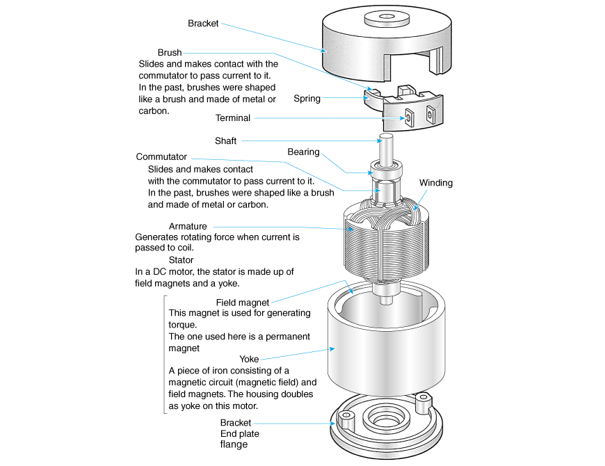
Structure of the DC Motor
Fig. 2.1 shows the structure and the names of respective parts of a DC motor used in plotters and copying machines, etc.
Compared with the motor used in a model, this motor has more coils and uses carbon brushes and roller bearings, and each mechanism is very sophisticated. But the basic structure and the principle of rotation are the same.