2-4-1. Structure and Operation of HB-type Motor
The basic rotor structure of an HB-type motor is shown in Fig. 2.47. An axially-magnetized cylindrical magnet is sandwiched between two steel rotors. The rotors are notched with teeth on their circumferences. The two rotors are installed so that they are 1/2 tooth pitch apart from each other when viewed from the shaft. The stator has multiple poles and each of them has a magnetizing coil. As with the rotors, these poles have teeth.

Fig. 2.48 is a schematic structure diagram of the HB motor that has been prepared to aid understanding of the principle of rotation.
The stator has multiple poles and each of them has a magnetizing coil. As with the rotors, these poles have teeth.
There are four stator windings as shown in the figure. Coils facing each other across the rotor are connected, making two groups of coils. The coils are connected in such a way that two opposing poles turn to the N-pole and S-pole, respectively, when energized. Here, assume that the top and bottom coils constitute phase A, while the right and left coils constitute phase B.
The rotor in the figure has 15 teeth. Suppose that the white rotor is located in the front and magnetized to the N-pole by the permanent magnet. And suppose that the teeth of the colored rotor are in the back side and magnetized to the S-pole.
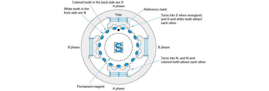
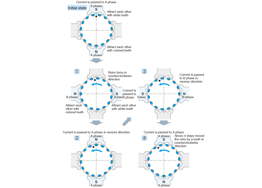
In Fig. 2.49, let's see how the motor rotates.
In the initial state, energize phase A so that the top pole in the figure becomes the S-pole and the bottom becomes the N-pole. Because the tooth on the white rotor is the N-pole, it attracts (and is attracted by) the S-pole in phase A, and because the tooth on the black rotor is the S-pole, it attracts (and is attracted by) the N-pole in phase A.
Change the energization state of the coils in the following sequence. The top tooth is indicated with the ● mark. Please check the change in the position.
- <1> Energize phase B so that the right-hand pole becomes the S-pole and the left-hand pole becomes the N-pole. The white tooth in the front and the right-hand pole attract each other, and the colored tooth in the back and left-hand pole attract each other. Now, the ● mark moved counterclockwise.
- <2> Energize phase A in the direction opposite to that of the energization performed in the initial state. The white tooth in the front and the bottom pole attract each other, and the colored tooth in the back and the top pole attract each other. Now, the ● mark moved further counterclockwise.
- <3> Energize phase B in the direction opposite to that of the energization performed in step <1>. The white tooth in the front and the left-hand pole attract each other, and the colored tooth in the back and the right-hand pole attract each other.
- <4> Energize phase A in the same way as the energization done in the initial state. The position of the ● mark is shifted from the initial state by one tooth.
As you see, by taking the four steps from <1> through <4>, the rotor has rotated counterclockwise by one tooth pitch.
To rotate the rotor clockwise, take the steps in reverse order (that is, from <4> to <1>).
Two-phase HB Motor
The motor described in the above section has two phases, A and B. These motors are called two-phase HB motors.
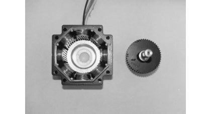
Fig. 2.50 shows an actual two-phase motor. This motor has 50 teeth.
Since a two-phase motor rotates one tooth distance in four steps, this motor requires 200 steps to make one revolution.
Eight coils are provided, and the opposite excited poles are connected so that they have the same polarity.
Since the attractive force in radial directions cancels each other in this structure, load to the bearing is reduced.
Winding a Coil
There are two ways to wind a coil.
One way of winding a single coil on one pole as shown in Fig. 2.51 (a) is called mono-filer winding.
The mono-filer winding increases coil use efficiency but requires four transistors in order to change the energization direction as shown in Fig. 2.52 (b). This is called a bipolar drive.

The other method of winding is to wind two layers of coils on a single pole (pole tooth) as shown in Fig. 2.51 (b). This is called bi-filer winding. The coil use efficiency of bi-filer winding is not as high as that of mono-filer winding, but, as shown in Fig. 2.52 (c), you can reverse the excitation by choosing which of the two transistors is to be energized.
In the diagram of bi-filer winding, magnetizing coils connected in the opposite direction to coils A and B are usually indicated by a line drawn above them and the letters A and B (Fig. 2.53).


In comparison with the five-phase HB motor to be described later, the two-phase HB motor has the following features:
- ・Most motors of this type require 200 steps to make one revolution.
- ・The drive circuit of this motor is simpler than that of a five-phase motor.
Five-phase HB Motor
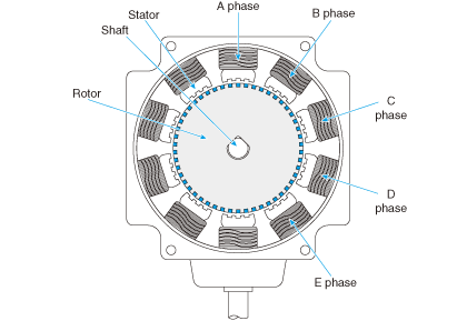
A five-phase HB motor uses five pairs of coils. The motor shown in Fig. 2.54 has 10 coils and 50 teeth. Just like two-phase motors, the opposing coils of this motor are designed to have the same polarity to prevent radial load from being generated.
Energization of the five-phase motor is carried out in the following order.
<1> Phase A is magnetized to the N-pole -> <2> Phase B to the S-pole -> <3> Phase C to the N-pole -> <4> Phase D to the S-pole -> <5> Phase E to the N-pole -> <6> Phase A to the S-pole -> <7> Phase B to the N-pole -> <8> Phase C to the S-pole -> <9> Phase D to the N-pole -> <10> Phase E to the S-pole
Through the above 10 steps, the rotor is rotated by one tooth. In one step, it is rotated by 0.72 degrees.
When compared with two-phase motors, five-phase motors have the following features:
- ・Division number per revolution is large.
- ・Torque fluctuations are small in the excited state.
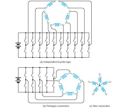
With a five-phase HB motor, you must handle many wires when leading the coil wires out as they are.
Therefore, in most cases, the wires of a five-phase motor are bundled together inside the motor before they are led out.
There are two ways to bundle the wires of a five-phase stepping motor together. One is the star connection in which the wires of each coil are all connected on one end. The other is the pentagon connection where adjacent coils are connected with each other (Fig. 2.55).
Since the excitation method differs between the star connection and pentagon connection, you must check the compatibility between the motor and the excitation method of the amplifier.
<Short column> Features of five-phase stepping motor
The pulse number for one revolution of a five-phase stepping motor is a multiple of 5. It may be, for example, 500 and 1000. On the other hand, the pulse number for a two-phase stepping motor may be 200, 400, and so on.
It is more convenient for automatic equipment when the distance of travel made by one motor revolution is, for example, 5 mm or 10 mm, rather than 2 mm. This is another reason why the five-phase motor is preferred over the two-phase stepping motor.