2-3-2. Rotation Principle of Induction Motor
As described in Chapter 1, there are many types of rotating magnetic field-type motors.
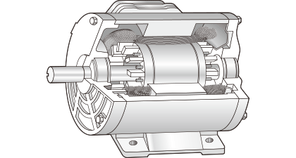
This chapter discusses power motors used at plants (Fig. 2.35) and induction motors widely used at home for electric fans and laundry machines.
An introductory book to motors explains the principle of rotation of induction motor using Arago' disc ( see Fig. 2.42 ).
The rotor of general induction motors has the structure shown in Fig. 2.36 (a). If you disassemble the rotor, you will see that it is not a disc and that it is composed of a silicon steel plate and a cage-shaped aluminum part as shown in Fig. 2.36 (b). Such a rotor is called a squirrel-cage rotor.
It is not appropriate to use Arago's disc to explain the principle of rotation of motors equipped with a squirrel-cage rotor. It can be better explained with the approach used for DC motors.

As shown in Fig. 2.37, a closed coil is placed in a magnetic field and the outside magnet is rotated. Then, as seen in the principle of power generation of DC motors, power-generation action occurs on the coil and current flows through the coil.
As current flows, the coil generates torque that interacts with the original magnetic field, and then the coil starts rotating.
If you increase the number of coils as shown in Fig. 2.38, you can replace the coils with a cage.
Namely, the cage of induction motors corresponds to the coil of DC motors.


The following summarizes the principle of rotation of induction motors.
- <1> Rotation of magnetic field
- <2> Generation of induction current
- <3> Generation of force from interaction between current and magnetic field
- <4> Rotation of rotor
On the actual motors, the mechanism sequentially excites a number of coils in place of moving the magnets to obtain the same effect. To change the excitation, two or more temporally-shifted sine waves are necessary.
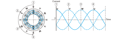
Generally, three-phase 200 VAC shifted by 120 degrees from each other is used at plants (Fig. 2.39).
Since the power supply for home use is single-phase 100 VAC, we must create, in one way or another, a sine wave shifted from that of the power supply when using an induction motor. One method is to advance the coil current phase by 90 degrees using a capacitor. A motor that runs in this fashion is called a capacitor-run single phase motor.
A capacitor-run single phase motor generates a rotating magnetic field with a set of two windings, one is the master winding that is connected directly to the power supply and the other is an auxiliary winding that is connected to the power supply via a capacitor.
The structure of a capacitor-run motor is shown in Fig. 1.2 of Chapter 1.